RM2660E
_56
Audio / Visual / Telematics
_052828
AUDIO / VIDEO
_0255476
REAR SEAT ENTERTAINMENT SYSTEM
J
AUDIO / VIDEO REAR SEAT ENTERTAINMENT SYSTEM Multi-display Controller Power Source Circuit
DESCRIPTION
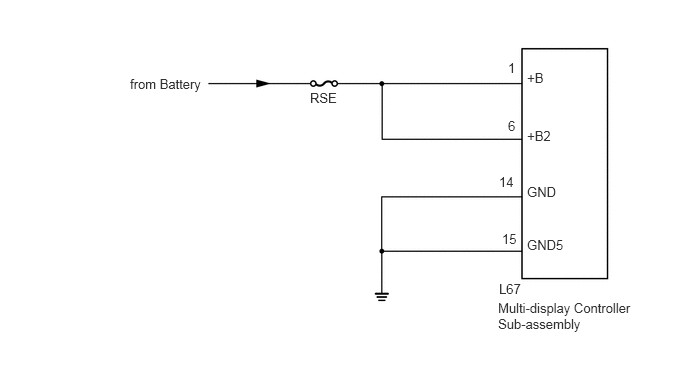
This is the power source circuit of the multi-display controller sub-assembly.
WIRING DIAGRAM
5.49,0.729 5.781,0.896
0.292,0.167
10
false
+B
5.49,1.917 5.875,2.083
0.385,0.167
10
false
GND
5.49,2.469 5.938,2.635
0.448,0.167
10
false
GND5
5.49,1.333 5.958,1.5
0.469,0.167
10
false
+B2
5.229,2.406 5.406,2.573
0.177,0.167
10
false
15
5.198,1.813 5.396,1.979
0.198,0.167
10
false
14
5.292,0.625 5.396,0.792
0.104,0.167
10
false
1
5.292,1.229 5.406,1.396
0.115,0.167
10
false
6
3.229,0.938 3.594,1.115
0.365,0.177
10
false
RSE
1.354,0.792 2.188,0.969
0.833,0.177
10
false
from Battery
5.188,3.125 6.688,3.51
1.5,0.385
10
false
Multi-display Controller Sub-assembly
5.198,2.927 5.5,3.104
0.302,0.177
10
false
L67
CAUTION / NOTICE / HINT
- NOTICE:
-
Inspect the fuses for circuits related to this system before performing the following inspection procedure.
PROCEDURE
1.CHECK HARNESS AND CONNECTOR (MULTI-DISPLAY CONTROLLER SUB-ASSEMBLY - BATTERY AND BODY GROUND)
a.
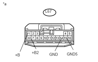
Disconnect the multi-display controller sub-assembly connector.
0.528,1.852 0.754,2.021
0.226,0.170
10
+B
1.113,1.77 1.430,1.940
0.317,0.170
10
+B2
1.066,1.318 1.264,1.726
false
0.982,1.155 0.703,1.821
false
2.157,1.357 1.925,1.799
false
1.728,1.834 2.076,2.004
0.348,0.170
10
GND
2.342,1.821 2.770,1.991
0.428,0.170
10
GND5
2.338,1.348 2.57,1.756
false
0.099,0.048 0.315,0.218
0.216,0.170
10
*a
1.586,0.309 1.894,0.459
0.308,0.150
10
L67
b.
Measure the resistance according to the value(s) in the table below.
- Standard Resistance:
Tester Connection Condition Specified Condition L67-14 (GND) - Body ground Always Below 1 Ω L67-15 (GND5) - Body ground Always Below 1 Ω
c.
Measure the voltage according to the value(s) in the table below.
- Standard Voltage:
Tester Connection Condition Specified Condition L67-1 (+B) - L67-14 (GND) Always 11 to 14 V L67-6 (+B2) - L67-14 (GND) Always 11 to 14 V
| *a | Front view of wire harness connector
(to Multi-display Controller Sub-assembly) |
OK
PROCEED TO NEXT SUSPECTED AREA SHOWN IN PROBLEM SYMPTOMS TABLE
(See pageAudio / Visual / Telematics>AUDIO / VIDEO>REAR SEAT ENTERTAINMENT SYSTEM>PROBLEM SYMPTOMS TABLE)
NG
REPAIR OR REPLACE HARNESS OR CONNECTOR