RM2660E
_56
Audio / Visual / Telematics
_052828
AUDIO / VIDEO
_0255476
REAR SEAT ENTERTAINMENT SYSTEM
J
AUDIO / VIDEO REAR SEAT ENTERTAINMENT SYSTEM Display Mode Signal Circuit between Multi-display Controller and Television Display Assembly
DESCRIPTION
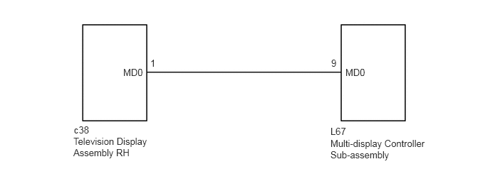
This is the display mode signal circuit between the multi-display controller sub-assembly and television display assembly RH.
WIRING DIAGRAM
1.802,0.979 2.177,1.135
0.375,0.156
10
false
MD0
5.052,0.979 5.417,1.167
0.365,0.188
10
false
MD0
2.198,0.844 2.365,1.031
0.167,0.188
10
false
1
4.844,0.844 5.031,1.021
0.188,0.177
10
false
9
4.833,2.021 6.354,2.396
1.521,0.375
10
false
Multi-display Controller Sub-assembly
1.073,1.99 2.177,2.354
1.104,0.365
10
false
Television Display Assembly RH
1.083,1.823 1.417,2
0.333,0.177
10
false
c38
4.833,1.844 5.198,2.01
0.365,0.167
10
false
L67
PROCEDURE
1.CHECK HARNESS AND CONNECTOR (MULTI-DISPLAY CONTROLLER SUB-ASSEMBLY - TELEVISION DISPLAY ASSEMBLY RH)
a.
Disconnect the L67 multi-display controller sub-assembly connector.
b.
Disconnect the c38 television display assembly RH connector.
c.
Measure the resistance according to the value(s) in the table below.
- Standard Resistance:
Tester Connection Condition Specified Condition L67-9 (MD0) - c38-1 (MD0) Always Below 1 Ω L67-9 (MD0) - Body ground Always 10 kΩ or higher
OK
PROCEED TO NEXT SUSPECTED AREA SHOWN IN PROBLEM SYMPTOMS TABLE
(See pageAudio / Visual / Telematics>AUDIO / VIDEO>REAR SEAT ENTERTAINMENT SYSTEM>PROBLEM SYMPTOMS TABLE)
NG
REPAIR OR REPLACE HARNESS OR CONNECTOR