RM2660E
_56
Audio / Visual / Telematics
_052828
AUDIO / VIDEO
_0255476
REAR SEAT ENTERTAINMENT SYSTEM
J
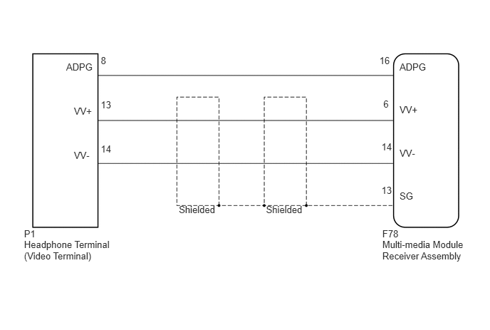
AUDIO / VIDEO REAR SEAT ENTERTAINMENT SYSTEM Display Signal Circuit between Radio Receiver and Video Terminal
DESCRIPTION
This is the display signal circuit from the video terminal to the multi-media module receiver assembly.
WIRING DIAGRAM
0.352,3.49 1.868,3.921
1.517,0.431
10
Headphone Terminal (Video Terminal)
0.352,3.331 0.650,3.505
0.298,0.174
10
P1
5.592,3.49 6.918,3.815
1.326,0.325
10
Multi-media Module Receiver Assembly
5.592,3.331 5.890,3.505
0.298,0.174
10
F78
5.844,0.892 6.283,1.067
0.439,0.174
10
ADPG
1.081,2.183 1.471,2.358
0.391,0.174
10
VV-
1.474,2.093 1.688,2.268
0.214,0.174
10
14
0.968,0.894 1.459,1.069
0.491,0.174
10
ADPG
1.474,0.804 1.688,0.979
0.214,0.174
10
8
1.081,1.539 1.505,1.713
0.425,0.174
10
VV+
1.474,1.449 1.688,1.623
0.214,0.174
10
13
5.844,2.786 6.310,2.960
0.466,0.174
10
SG
5.579,2.696 5.793,2.870
0.214,0.174
10
13
5.844,2.155 6.235,2.329
0.391,0.174
10
VV-
5.579,2.065 5.793,2.240
0.214,0.174
10
14
5.844,1.523 6.269,1.698
0.425,0.174
10
VV+
5.549,0.804 5.757,0.979
0.208,0.174
10
16
5.607,1.435 5.821,1.609
0.214,0.174
10
6
3.891,2.978 4.501,3.157
0.610,0.179
10
Shielded
2.616,2.978 3.226,3.157
0.610,0.179
10
Shielded
PROCEDURE
1.CHECK HARNESS AND CONNECTOR (MULTI-MEDIA MODULE RECEIVER ASSEMBLY - VIDEO TERMINAL)
a.
Disconnect the F78 multi-media module receiver assembly connector.
b.
Disconnect the P1 headphone terminal (video terminal) connector.
c.
Measure the resistance according to the value(s) in the table below.
- Standard Resistance:
Tester Connection Condition Specified Condition F78-6 (VV+) - P1-13 (VV+) Always Below 1 Ω F78-14 (VV-) - P1-14 (VV-) Always Below 1 Ω F78-16 (ADPG) - P1-8 (ADPG) Always Below 1 Ω F78-6 (VV+) - Body ground Always 10 kΩ or higher F78-14 (VV-) - Body ground Always 10 kΩ or higher F78-13 (SG) - Body ground Always 10 kΩ or higher F78-16 (ADPG) - Body ground Always 10 kΩ or higher
OK
PROCEED TO NEXT SUSPECTED AREA SHOWN IN PROBLEM SYMPTOMS TABLE
(See pageAudio / Visual / Telematics>AUDIO / VIDEO>REAR SEAT ENTERTAINMENT SYSTEM>PROBLEM SYMPTOMS TABLE)
NG
REPAIR OR REPLACE HARNESS OR CONNECTOR