RM2660E
_56
Audio / Visual / Telematics
_052828
AUDIO / VIDEO
_0255488
AUDIO AND VISUAL SYSTEM(w/ Multi-display)
J
AUDIO / VIDEO AUDIO AND VISUAL SYSTEM(w/ Multi-display) Display Signal Circuit between Radio Receiver and Stereo Jack Adapter
DESCRIPTION
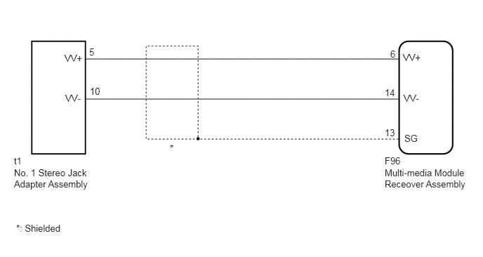
The No. 1 stereo jack adapter assembly sends the display signal from an external device to the multi-media module receiver assembly via this circuit.
WIRING DIAGRAM
5.979,0.771 6.438,0.969
0.458,0.198
10
false
VV+
5.99,1.375 6.448,1.573
0.458,0.198
10
false
VV-
6,1.969 6.458,2.167
0.458,0.198
10
false
SG
5.708,2.302 5.99,2.469
0.281,0.167
10
false
F96
5.708,2.479 7,2.896
1.292,0.417
10
false
Multi-media Module Receover Assembly
0.958,0.781 1.417,0.979
0.458,0.198
10
false
VV+
0.969,1.375 1.427,1.573
0.458,0.198
10
false
VV-
5.708,1.885 5.958,2.042
0.25,0.156
10
false
13
5.708,1.292 5.958,1.448
0.25,0.156
10
false
14
5.792,0.719 5.969,0.875
0.177,0.156
10
false
6
2.521,2.115 3.031,2.281
0.51,0.167
10
false
*
0.208,2.302 0.438,2.469
0.229,0.167
10
false
t1
0.208,2.479 1.417,2.917
1.208,0.438
10
false
No. 1 Stereo Jack Adapter Assembly
1.323,0.688 1.573,0.844
0.25,0.156
10
false
5
1.333,1.271 1.583,1.427
0.25,0.156
10
false
10
0.24,3.302 0.948,3.5
0.708,0.198
10
false
*: Shielded
PROCEDURE
1.CHECK HARNESS AND CONNECTOR (MULTI-MEDIA MODULE RECEIVER ASSEMBLY - NO. 1 STEREO JACK ADAPTER ASSEMBLY)
a.
Disconnect the F96 multi-media module receiver assembly connector.
b.
Disconnect the t1 No. 1 stereo jack adapter assembly connector.
c.
Measure the resistance according to the value(s) in the table below.
- Standard Resistance:
Tester Connection Condition Specified Condition F96-6 (VV+) - t1-5 (VV+) Always Below 1 Ω F96-14 (VV-) - t1-10 (VV-) Always Below 1 Ω F96-6 (VV+) or t1-5 (VV+) - Body ground Always 10 kΩ or higher F96-14 (VV-) or t1-10 (VV-) - Body ground Always 10 kΩ or higher F96-13 (SG) - Body ground Always 10 kΩ or higher
OK
PROCEED TO NEXT SUSPECTED AREA SHOWN IN PROBLEM SYMPTOMS TABLE
NG
REPAIR OR REPLACE HARNESS OR CONNECTOR