PARK ASSIST / MONITORING MULTI-TERRAIN MONITOR SYSTEM ECU Power Source Circuit
DESCRIPTION
This circuit provides power to operate the parking assist ECU.
WIRING DIAGRAM
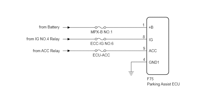
CAUTION / NOTICE / HINT
- NOTICE:
- ·
When "!" mark is displayed on the multi-display after the cable is disconnected from the negative (-) battery terminal, correct the steering angle neutral point (See page Audio / Visual / Telematics>PARK ASSIST / MONITORING>MULTI-TERRAIN MONITOR SYSTEM>INITIALIZATION).
·Depending on the parts that are replaced or operations that are performed during vehicle inspection or maintenance, calibration of other systems as well as the multi-terrain monitor system may be needed (See page General>INTRODUCTION>REPAIR INSTRUCTION>INITIALIZATION).
·Inspect the fuses for circuits related to this system before performing the following inspection procedure.
PROCEDURE
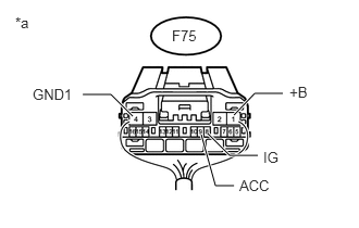
Disconnect the parking assist ECU connector.
Measure the resistance according to the value(s) in the table below.
- Standard Resistance:
Tester Connection Condition Specified Condition F75-4 (GND1) - Body ground Always Below 1 Ω
Measure the voltage according to the value(s) in the table below.
- Standard Voltage:
Tester Connection Condition Specified Condition F75-1 (+B) - Body ground Always 11 to 14 V F75-8 (IG) - Body ground Engine switch on (IG) 11 to 14 V F75-9 (ACC) - Body ground Engine switch on (ACC) 11 to 14 V
| *a | Rear view of wire harness connector
(to Parking Assist ECU) |
OK
NG