Home › Power Source / Network › 1VD-FTV (BATTERY / CHARGING) › GENERATOR
RM2660E _57 Power Source / Network _052833 1VD-FTV BATTERY / CHARGING _0255523 GENERATOR A

1VD-FTV BATTERY / CHARGING  GENERATOR  REASSEMBLY  


PROCEDURE

Hide 27330 1.INSTALL GENERATOR ROTOR ASSEMBLY
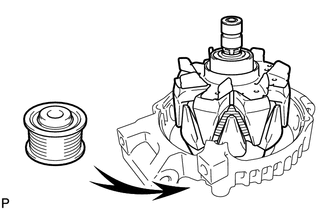
a.
A163025

Place the drive end frame on the pulley.


b.

Install the rotor to the drive end frame.


Hide 27360 2.INSTALL GENERATOR COIL ASSEMBLY
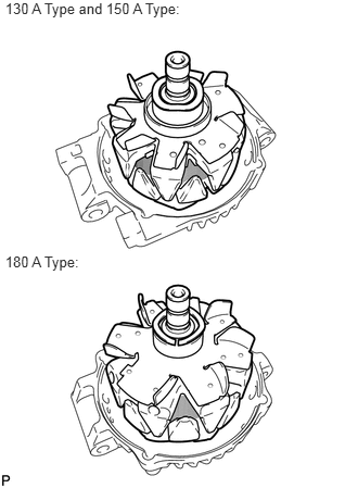
a.
A178036E01
0.05,0 1.915,0.211 1.865,0.211 10 130 A Type and 150 A Type: 0.05,2.427 0.867,2.633 0.817,0.206 10 180 A Type:

Place the generator washer on the rotor.
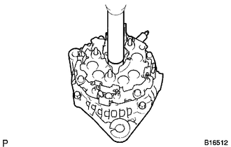

b.
B016512

Using a 21 mm socket wrench and a press, slowly press in the coil assembly.
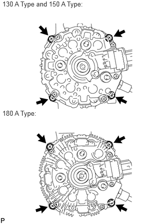

c.
A178034E01
0.049,0 1.872,0.198 1.823,0.198 10 130 A Type and 150 A Type: 0.049,2.284 0.858,2.481 0.809,0.198 10 180 A Type:

130 A Type and 150 A Type:

Install the 4 bolts.

Torque:
5.8 N*m (59 kgf*cm, 51 in.*lbf)


d.

180 A Type:

Install the 4 bolts.

Torque:
7.5 N*m (76 kgf*cm, 66 in.*lbf)


Hide 27370 3.INSTALL GENERATOR BRUSH HOLDER ASSEMBLY
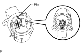
a.
A163028E01
1.407,0.093 1.667,0.276 0.260,0.183 10 Pin 0.734,0.72 1.276,0.173 false 1.271,0.173 1.357,0.173 false

While pushing the 2 brushes toward the inside of the brush holder, insert a pin (diameter: 1.0 mm (0.0394 in.)) into the brush holder hole.
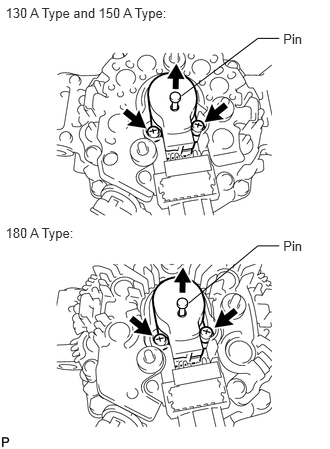

b.
A178043E01
0.058,0.052 1.877,0.253 1.819,0.201 10 130 A Type and 150 A Type: 0.058,2.34 0.845,2.544 0.788,0.205 10 180 A Type: 2.95,0.323 3.217,0.507 0.267,0.184 10 Pin 2.95,2.476 3.217,2.660 0.267,0.184 10 Pin 2.909,2.561 2.685,2.561 2.685,2.561 1.965,3.158 false 2.909,0.4 2.685,0.4 2.685,0.4 1.891,0.998 false

Install the generator brush holder with the 2 screws.

Torque:
1.8 N*m (18 kgf*cm, 16 in.*lbf)


c.

Pull out the pin from the generator brush holder.


Hide 27039 4.INSTALL GENERATOR REAR END COVER
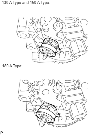
a.
A178032E01
0.064,0 1.882,0.198 1.818,0.198 10 130 A Type and 150 A Type: 0.072,2.199 0.885,2.404 0.813,0.205 10 180 A Type:

Install the terminal insulator to the generator rectifier end frame.

NOTICE:

Pay attention to the mounting orientation of the terminal insulator.
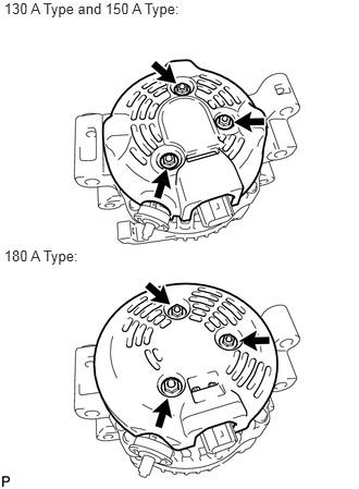


b.
A178044E01
0.039,0 1.857,0.193 1.818,0.193 10 130 A Type and 150 A Type: 0.039,2.366 0.861,2.559 0.823,0.193 10 180 A Type:

Install the end cover with the 3 nuts.

Torque:
4.6 N*m (46 kgf*cm, 40 in.*lbf)


Hide 27411 5.INSTALL GENERATOR PULLEY

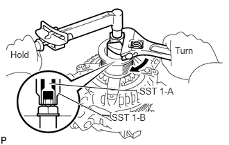
A156429E02
0.74,1.26 1.875,1.365 true 1.875,1.365 2.052,1.365 false 0.875,1.406 1.531,1.74 true 1.531,1.74 1.646,1.74 false 2.625,0.677 2.969,0.833 0.344,0.156 10 false Turn 0.156,0.74 0.49,0.896 0.333,0.156 10 false Hold 2.094,1.292 2.729,1.563 0.635,0.271 10 true SST 1-A 1.677,1.688 2.375,1.969 0.698,0.281 10 true SST 1-B

SST
09820-63011  (09820-06010, 09820-06021)

HINT:
SST 1-A and 1-B 09820-06010
SST 2 09820-06021


a.

Install the pulley onto the rotor shaft by tightening the pulley nut by hand.


b.

Hold SST 1-A with a torque wrench, and tighten SST 1-B clockwise to the specified torque.

Torque:
39 N*m (398 kgf*cm, 29 ft.*lbf)

NOTICE:

Check that SST is secured to the rotor shaft.
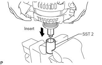


c.
A156430E01
0.814,0.876 1.216,1.046 0.402,0.170 10 Insert 2.777,1.063 3.218,1.233 0.441,0.170 10 SST 2 1.868,1.511 2.649,1.145 false 2.646,1.145 2.76,1.145 false

Mount SST 2 in a vise.


d.

Insert SST 1-A and B into SST 2, and attach the pulley nut to SST 2.
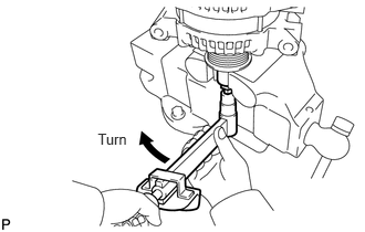

e.
A163027E01
0.92,1.225 1.240,1.391 0.321,0.166 10 Turn

Tighten the pulley nut by turning SST 1-A in the direction shown in the illustration.

Torque:
133 N*m (1351 kgf*cm, 98 ft.*lbf)


f.

Remove the generator from SST 2.


g.
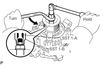
A156432E02
0.698,1.167 1.844,1.271 false 1.833,1.271 2.021,1.271 false 0.844,1.313 1.5,1.646 false 1.5,1.646 1.615,1.646 false 0.292,0.531 0.635,0.688 0.344,0.156 10 false Turn 2.781,0.563 3.115,0.719 0.333,0.156 10 false Hold 2.063,1.198 2.656,1.458 0.594,0.26 10 true SST 1-A 1.646,1.563 2.302,1.854 0.656,0.292 10 true SST 1-B

Turn SST 1-B, and remove SST 1-A and 1-B.


h.

Turn the pulley and check that the pulley moves smoothly.