NETWORKING CAN COMMUNICATION SYSTEM(for LHD) B2621 Communication Interruption
DESCRIPTION
The multiplex tilt and telescopic ECU forms a network with the ECUs of other systems through the CAN communication bus, each ECU informs the other ECUs that it is connected to the network by outputting a specified signal (periodic signal) onto the CAN communication bus on a regular schedule. The multiplex tilt and telescopic ECU detects the connection of each ECU based on the signal.
| DTC Code | DTC Detection Condition | Trouble Area |
|---|---|---|
| B2621 | Periodic signal from the specified ECU has stopped. | ·
MS bus circuit ·
Multiplex tilt and telescopic ECU branch wire or connector ·
Main body ECU (cowl side junction block LH) CAN main wire or connector ·
Multiplex tilt and telescopic ECU ·
Main body ECU (cowl side junction block LH) |
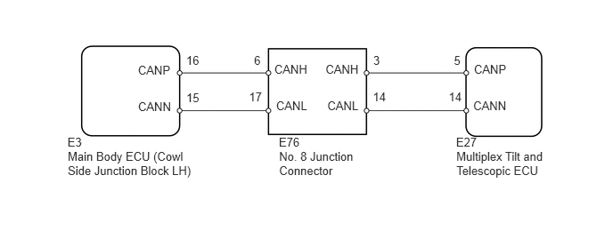
WIRING DIAGRAM
PROCEDURE
Check for DTCs (See page Power Source / Network>NETWORKING>CAN COMMUNICATION SYSTEM(for LHD)>DIAGNOSIS SYSTEM).
| Result | Proceed to |
|---|---|
| DTC B2621 is output alone | A |
| DTC B2621 and U1115 and/or U1002 are output | B |
- HINT:
-
When DTC B2621 and U1115 and/or U1002 are output simultaneously, perform the troubleshooting for DTC U1115 and/or U1002 first.
A
B
(See pagePower Source / Network>NETWORKING>CAN COMMUNICATION SYSTEM(for LHD)>DIAGNOSTIC TROUBLE CODE CHART)