RM2660E
_57
Power Source / Network
_052837
NETWORKING
_0255538
CAN COMMUNICATION SYSTEM(for RHD without Central Gateway ECU)
U
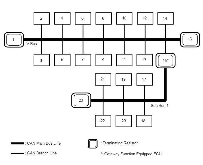
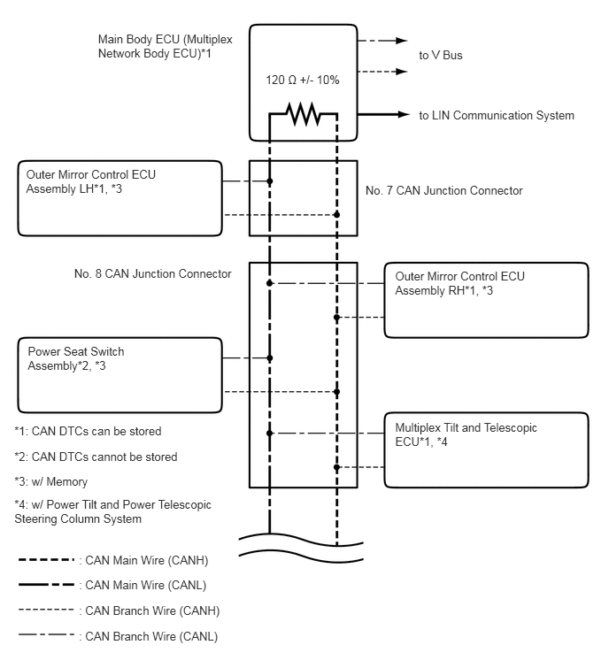
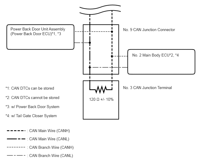
NETWORKING CAN COMMUNICATION SYSTEM(for RHD without Central Gateway ECU) SYSTEM DIAGRAM
SYSTEM DIAGRAM
0.938,1.458 2.292,1.813
1.354,0.354
10
false
V Bus
5.323,3.646 6.365,4
1.042,0.354
10
false
Sub Bus 1
0.427,1.313 1.208,1.896
0.781,0.583
10
false
1
1.417,0.563 2.198,1.146
0.781,0.583
10
false
2
1.406,2.052 2.188,2.635
0.781,0.583
10
false
3
5.74,2.052 6.208,2.5
0.469,0.448
10
false
15
2.146,0.552 2.5,0.729
0.354,0.177
10
false
4
2.156,2.021 2.51,2.198
0.354,0.177
10
false
5
2.875,0.563 3.229,0.74
0.354,0.177
10
false
6
4.302,2.021 4.656,2.198
0.354,0.177
10
false
11
5.031,0.552 5.385,0.729
0.354,0.177
10
false
12
5.01,2.031 5.365,2.208
0.354,0.177
10
false
13
5.75,0.563 6.104,0.74
0.354,0.177
10
false
14
3.604,2.031 3.958,2.208
0.354,0.177
10
false
9
4.313,0.552 4.667,0.729
0.354,0.177
10
false
10
2.875,2.021 3.229,2.198
0.354,0.177
10
false
7
3.604,0.563 3.958,0.74
0.354,0.177
10
false
8
6.625,1.292 6.979,1.469
0.354,0.177
10
false
16
5.01,2.719 5.365,2.896
0.354,0.177
10
false
17
4.979,4.188 5.333,4.365
0.354,0.177
10
false
18
4.281,2.719 4.635,2.896
0.354,0.177
10
false
19
4.292,4.188 4.646,4.365
0.354,0.177
10
false
20
3.552,2.708 3.906,2.885
0.354,0.177
10
false
21
3.552,4.188 3.906,4.365
0.354,0.177
10
false
22
2.781,3.458 3.135,3.635
0.354,0.177
10
false
23
5.896,2.052 6.677,2.635
0.781,0.583
10
false
*
0.885,4.979 2.958,5.208
2.073,0.229
10
false
: CAN Main Bus Line
0.885,5.323 2.958,5.552
2.073,0.229
10
false
: CAN Branch Line
3.552,4.969 5.625,5.198
2.073,0.229
10
false
: Terminating Resistor
3.552,5.354 5.99,5.583
2.438,0.229
10
false
*: Gateway Function Equipped ECU
| No. | ECU/Sensor name |
|---|---|
| 1 | ECM |
| 2 | DLC3 |
| 3 | 4WD Control ECU |
| 4 | Tire Pressure Warning ECU*1 |
| 5 | Airbag Sensor Assembly |
| 6 | Air Conditioning Amplifier Assembly |
| 7 | Headlight Leveling ECU Assembly |
| 8 | Master Cylinder Solenoid (Skid Control ECU) |
| 9 | Steering Control ECU*2 |
| 10 | Certification ECU (Smart Key ECU Assembly)*3 |
| 11 | Power Steering ECU Assembly*4 |
| 12 | Steering Sensor |
| 13 | Bus Buffer ECU*5 |
| 14 | ·
Multi-media Module Receiver Assembly*6 ·
Option Connector*7 |
| 15 | Main Body ECU (Multiplex Network Body ECU) |
| 16 | Combination Meter Assembly |
| 17 | Outer Mirror Control ECU Assembly RH*8 |
| 18 | Outer Mirror Control ECU Assembly LH*8 |
| 19 | Power Seat Switch Assembly*8 |
| 20 | Multiplex Tilt and Telescopic ECU*9 |
| 21 | Power Back Door Unit Assembly (Power Back Door ECU)*11 |
| 22 | No. 2 Main Body ECU*11 |
| 23 | No. 3 CAN Junction Terminal |
*1: w/ Tire Pressure Warning System
*2: w/ Variable Gear Ratio Steering System
*3: w/ Entry and Start System
*4: w/ Variable Flow Control Solenoid Valve
*5: w/ Bus Buffer ECU
*6: for Multi-media Module Receiver Type
*7: Option Connector
*8: w/ Memory
*9: w/ Power Tilt and Power Telescopic Steering Column System
*10: w/ Power Back Door System
*11: w/ Tail Gate Closer System
- HINT:
- ·
The main body ECU (multiplex network body ECU) functions as a gateway between the V bus and sub bus 1.
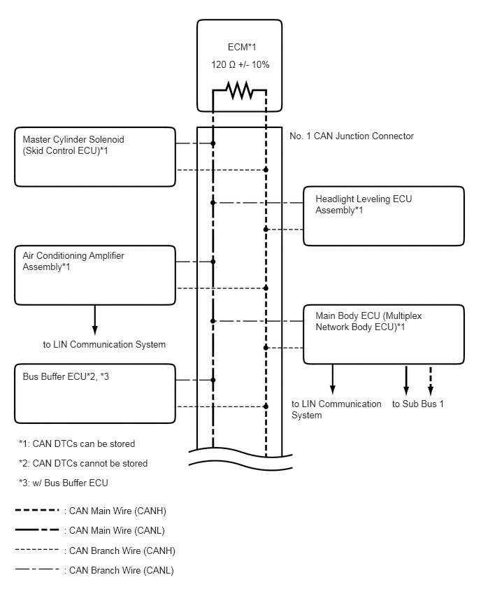
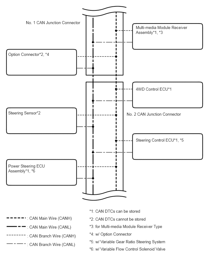
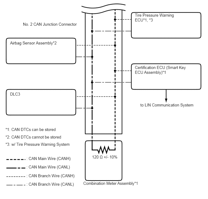
·Refer to the following bus wiring diagrams for details.
V BUS
3.394,0.612 3.876,0.962
0.482,0.350
10
ECM*1
3.145,0.878 4.062,1.058
0.916,0.180
10
120 Ω +/- 10%
0.338,3.723 1.990,4.198
1.652,0.475
10
Air Conditioning Amplifier Assembly*1
0.338,5.516 1.990,5.991
1.652,0.475
10
Bus Buffer ECU*2, *3
0.642,5.041 2.639,5.516
1.998,0.475
10
to LIN Communication System
0.282,6.517 2.907,6.659
2.625,0.142
10
*1: CAN DTCs can be stored
0.282,6.81 2.907,6.952
2.625,0.142
10
*2: CAN DTCs cannot be stored
0.282,7.102 2.907,7.244
2.625,0.142
10
*3: w/ Bus Buffer ECU
0.955,7.519 3.580,7.661
2.625,0.142
10
: CAN Main Wire (CANH)
0.955,7.813 3.580,7.955
2.625,0.142
10
: CAN Main Wire (CANL)
0.955,8.114 3.580,8.256
2.625,0.142
10
: CAN Branch Wire (CANH)
0.955,8.409 3.580,8.551
2.625,0.142
10
: CAN Branch Wire (CANL)
4.702,2.878 6.375,3.319
1.673,0.441
10
Headlight Leveling ECU Assembly*1
0.338,1.985 2.011,2.425
1.673,0.441
10
Master Cylinder Solenoid (Skid Control ECU)*1
4.314,1.942 6.442,2.431
2.128,0.489
10
No. 1 CAN Junction Connector
4.345,5.928 5.771,6.403
1.426,0.475
10
to LIN Communication System
5.844,5.928 6.710,6.403
0.866,0.475
10
to Sub Bus 1
4.702,4.618 6.418,5.380
1.716,0.762
10
Main Body ECU (Multiplex Network Body ECU)*1
3.052,7.125 5.604,7.281
2.552,0.156
10
false
*1: CAN DTCs can be stored
3.052,7.396 5.781,7.542
2.729,0.146
10
false
*2: CAN DTCs cannot be stored
3.052,7.646 5.729,7.792
2.677,0.146
10
false
*3: for Multi-media Module Receiver Type
3.052,7.906 5.802,8.052
2.75,0.146
10
false
*4: w/ Option Connector
3.052,8.167 5.729,8.313
2.677,0.146
10
false
*5: w/ Variable Gear Ratio Steering System
3.052,8.417 5.802,8.563
2.75,0.146
10
false
*6: w/ Variable Flow Control Solenoid Valve
0.927,7.365 3.552,7.51
2.625,0.146
10
false
: CAN Main Wire (CANH)
0.927,7.667 3.594,7.844
2.667,0.177
10
false
: CAN Main Wire (CANL)
0.927,7.969 3.552,8.115
2.625,0.146
10
false
: CAN Branch Wire (CANH)
0.927,8.26 3.552,8.406
2.625,0.146
10
false
: CAN Branch Wire (CANL)
0.281,3.771 2.031,4.229
1.75,0.458
10
false
Steering Sensor*2
0.281,1.771 2.583,2.24
2.302,0.469
10
false
Option Connector*2, *4
4.635,0.854 6.938,1.323
2.302,0.469
10
false
Multi-media Module Receiver Assembly*1, *3
4.635,4.698 6.458,5.135
1.823,0.438
10
false
Steering Control ECU*1, *5
4.635,2.958 6.313,3.396
1.677,0.438
10
false
4WD Control ECU*1
0.281,5.583 1.677,5.917
1.396,0.333
10
false
Power Steering ECU Assembly*1, *6
0.885,0.688 3.885,1.219
3,0.531
10
false
No. 1 CAN Junction Connector
4.323,3.813 6.677,4.344
2.354,0.531
10
false
No. 2 CAN Junction Connector
4.835,3.535 6.833,4.010
1.998,0.475
10
to LIN Communication System
0.189,4.376 2.735,4.587
2.547,0.210
10
*1: CAN DTCs can be stored
0.189,4.633 2.923,4.820
2.734,0.187
10
*2: CAN DTCs cannot be stored
0.189,4.888 2.869,5.030
2.681,0.142
10
*3: w/ Tire Pressure Warning System
0.911,5.373 3.535,5.515
2.625,0.142
10
: CAN Main Wire (CANH)
0.911,5.67 3.579,5.849
2.668,0.179
10
: CAN Main Wire (CANL)
0.911,5.968 3.535,6.110
2.625,0.142
10
: CAN Branch Wire (CANH)
0.911,6.262 3.535,6.404
2.625,0.142
10
: CAN Branch Wire (CANL)
2.869,6.233 5.126,6.454
2.258,0.221
10
Combination Meter Assembly*1
3.171,5.327 4.087,5.507
0.916,0.180
10
120 Ω +/- 10%
4.648,2.24 6.471,3.223
1.823,0.982
10
Certification ECU (Smart Key ECU Assembly)*1
0.347,1.394 2.182,1.646
1.835,0.253
10
Airbag Sensor Assembly*2
0.347,3.159 2.182,3.412
1.835,0.253
10
DLC3
4.648,0.44 6.130,1.096
1.482,0.656
10
Tire Pressure Warning ECU*1, *3
0.792,0.749 2.892,1.072
2.100,0.323
10
No. 2 CAN Junction Connector
SUB BUS 1
4.932,0.559 6.132,0.701
1.200,0.142
10
to V Bus
4.932,1.274 6.928,1.416
1.996,0.142
10
to LIN Communication System
3.124,0.853 4.410,1.076
1.286,0.223
10
120 Ω +/- 10%
1.154,0.377 2.842,0.714
1.688,0.336
10
Main Body ECU (Multiplex Network Body ECU)*1
0.308,1.974 2.381,2.482
2.073,0.508
10
Outer Mirror Control ECU Assembly LH*1, *3
4.651,3.17 6.724,3.678
2.073,0.508
10
Outer Mirror Control ECU Assembly RH*1, *3
4.651,4.944 6.724,5.452
2.073,0.508
10
Multiplex Tilt and Telescopic ECU*1, *4
4.301,2.161 6.536,2.382
2.235,0.221
10
No. 7 CAN Junction Connector
0.873,3.137 3.108,3.358
2.235,0.221
10
No. 8 CAN Junction Connector
0.327,4.048 2.159,4.556
1.832,0.508
10
Power Seat Switch Assembly*2, *3
0.169,4.992 2.793,5.134
2.625,0.142
10
*1: CAN DTCs can be stored
0.169,5.288 2.793,5.430
2.625,0.142
10
*2: CAN DTCs cannot be stored
0.169,5.583 2.793,5.725
2.625,0.142
10
*3: w/ Memory
0.169,5.85 2.704,6.182
2.535,0.332
10
*4: w/ Power Tilt and Power Telescopic Steering Column System
0.929,6.512 3.554,6.654
2.625,0.142
10
: CAN Main Wire (CANH)
0.929,6.806 3.554,6.948
2.625,0.142
10
: CAN Main Wire (CANL)
0.929,7.108 3.554,7.250
2.625,0.142
10
: CAN Branch Wire (CANH)
0.929,7.402 3.554,7.544
2.625,0.142
10
: CAN Branch Wire (CANL)
0.196,3.382 2.820,3.524
2.625,0.142
10
*2: CAN DTCs cannot be stored
0.196,3.055 2.820,3.197
2.625,0.142
10
*1: CAN DTCs can be stored
0.196,4.036 2.820,4.178
2.625,0.142
10
*4: w/ Tail Gate Closer System
0.196,3.709 2.820,3.851
2.625,0.142
10
*3: w/ Power Back Door System
0.967,4.56 3.591,4.702
2.625,0.142
10
: CAN Main Wire (CANH)
0.967,4.854 3.591,4.996
2.625,0.142
10
: CAN Main Wire (CANL)
0.967,5.155 3.591,5.297
2.625,0.142
10
: CAN Branch Wire (CANH)
0.967,5.45 3.591,5.592
2.625,0.142
10
: CAN Branch Wire (CANL)
3.176,3.448 4.092,3.629
0.916,0.180
10
120 Ω +/- 10%
4.389,0.97 6.517,1.459
2.128,0.489
10
No. 9 CAN Junction Connector
4.718,1.88 6.846,2.370
2.128,0.489
10
No. 2 Main Body ECU*2, *4
0.375,0.949 2.503,1.438
2.128,0.489
10
Power Back Door Unit Assembly (Power Back Door ECU)*1, *3
4.389,3.029 6.517,3.519
2.128,0.489
10
No. 3 CAN Junction Terminal