RM2660E
_58
Vehicle Interior
_052838
DOOR LOCK
_0255554
BACK DOOR LOCK(for Double Swing Out Type)
G
DOOR LOCK BACK DOOR LOCK(for Double Swing Out Type) INSPECTION
PROCEDURE

 69110A
1.INSPECT BACK DOOR LOCK ASSEMBLY
a.
0.251,0.665 0.459,0.848
0.208,0.183
10
*a
0.265,1.713 0.473,1.896
0.208,0.183
10
*b
2.623,2.833 2.881,3.034
0.258,0.201
10
S
0.88,2.833 1.139,3.034
0.258,0.201
10
E
1.918,3.067 2.362,3.236
0.444,0.169
10
ACT+
1.31,3.067 1.689,3.228
0.379,0.161
10
ACT-
2.197,2.531 2.623,2.833
false
1.422,2.546 0.948,2.833
false
1.651,2.586 1.502,3.042
false
1.976,2.573 2.104,3.046
false
0.775,1.959 0.983,2.142
0.208,0.183
10
*c
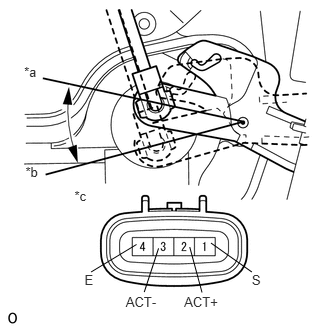
Check the operation of the door lock motor.
i.
Apply battery voltage to the door lock motor connector and check the operation of the door lock motor.
- OK:
Measurement Condition Specified Condition Battery positive (+) → Terminal 2 (ACT+)
Battery negative (-) → Terminal 3 (ACT-)Lock Battery positive (+) → Terminal 3 (ACT-)
Battery negative (-) → Terminal 2 (ACT+)Unlock
If the result is not as specified, replace the back door lock assembly.
| *a | Lock |
| *b | Unlock |
| *c | Component without harness connected
(Back Door Lock Assembly) |
b.
Check the detection switch.
i.
Measure the resistance according to the value(s) in the table below.
- Standard Resistance:
Tester Connection Switch Condition Specified Condition 1 (S) - 4 (E) Lock 10 kΩ or higher Unlock Below 1 Ω
If the result is not as specified, replace the back door lock assembly.
c.
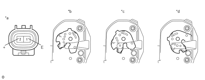
Check the operation of the door courtesy switch.
0.172,0.538 0.397,0.750
0.226,0.212
10
*a
2.374,0.314 2.600,0.525
0.226,0.212
10
*b
4.231,0.314 4.457,0.525
0.226,0.212
10
*c
6.155,0.314 6.380,0.525
0.226,0.212
10
*d
1.429,1.574 1.595,1.750
0.166,0.176
10
E
0.105,1.574 0.253,1.729
0.148,0.155
10
+
0.982,1.346 1.429,1.574
false
0.654,1.346 0.169,1.59
false
| *a | Component without harness connected
(Back Door Lock Assembly) |
*b | Full Latch |
| *c | Half Latch | *d | Open |
i.
Measure the resistance according to the value(s) in the table below.
- Standard Resistance:
Tester Connection Condition Specified Condition 1 (E) - 2 (+) Open Below 1 Ω Half Latch Below 1 Ω Full Latch 10 kΩ or higher
If the result is not as specified, replace the back door lock assembly.