RM2660E
_58
Vehicle Interior
_052839
THEFT DETERRENT / KEYLESS ENTRY
_0255570
ENTRY AND START SYSTEM(for Start Function)
C
THEFT DETERRENT / KEYLESS ENTRY ENTRY AND START SYSTEM(for Start Function) B2274 ACC Monitor Malfunction
DESCRIPTION
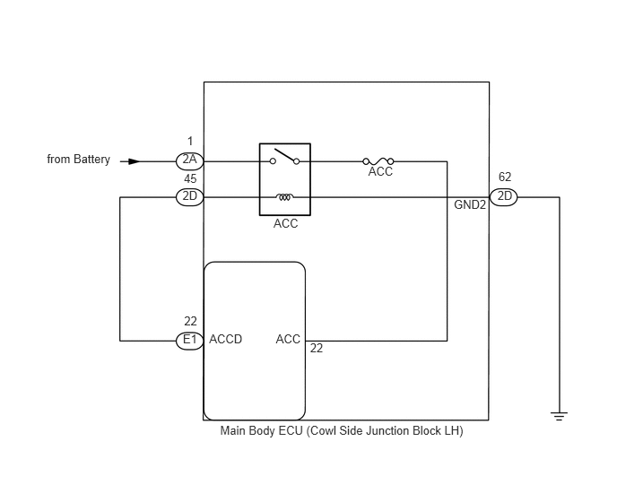
This DTC is stored when a malfunction occurs in the ACCD output circuit, which is between the ACC relay actuation circuit inside the main body ECU and the ACC relay.
| DTC Code | Detection Condition | Trouble Area |
|---|---|---|
| B2274 | The ACC relay actuation circuit inside the main body ECU or other related circuit is malfunctioning. | ·
Main body ECU ·
Harness or connector |
WIRING DIAGRAM
4.279,1.91 4.801,2.095
0.522,0.185
10
ACC
3.178,2.508 3.752,2.692
0.574,0.185
10
ACC
0.545,1.763 1.402,1.948
0.856,0.185
10
from Battery
2.12,1.763 2.428,1.948
0.308,0.185
10
2A
2.124,3.856 2.432,4.041
0.308,0.185
10
E1
5.779,2.184 6.044,2.368
0.265,0.185
10
2D
5.791,1.971 6.056,2.156
0.265,0.185
10
62
2.12,2.184 2.385,2.368
0.265,0.185
10
2D
2.135,1.989 2.400,2.174
0.265,0.185
10
45
2.139,3.651 2.404,3.836
0.265,0.185
10
22
2.171,1.556 2.335,1.741
0.164,0.185
10
1
2.43,3.856 2.911,4.041
0.480,0.185
10
ACCD
3.205,3.856 3.566,4.041
0.361,0.185
10
ACC
5.271,2.294 5.705,2.479
0.434,0.185
10
GND2
2.557,4.917 6.146,5.102
3.589,0.185
10
Main Body ECU (Cowl Side Junction Block LH)
3.602,3.955 3.833,4.140
0.231,0.185
10
22
PROCEDURE
1.READ VALUE USING INTELLIGENT TESTER (ACC RELAY MONITOR)
a.
Use the Data List to check if the ACC relay is functioning properly.
| Tester Display | Measurement Item/Range | Normal Condition | Diagnostic Note |
|---|---|---|---|
| ACC Relay Monitor | ACC relay monitor/ON or OFF | ON: Engine switch on (IG)
OFF: Engine switch off |
- |
- OK:
When the engine switch is turned on (IG), ON is displayed on the intelligent tester.
OK
2.CHECK WHETHER DTC OUTPUT RECURS
NG
3.CHECK HARNESS AND CONNECTOR (MAIN BODY ECU - BATTERY AND BODY GROUND)
2.CHECK WHETHER DTC OUTPUT RECURS
a.
b.
Turn the engine switch on (IG), wait at least 10 seconds, and check whether DTC B2274 is output.
| Result | Proceed to |
|---|---|
| No DTC output | A |
| DTC B2274 output | B |
A
USE SIMULATION METHOD TO CHECK
(See pageGeneral>INTRODUCTION>HOW TO TROUBLESHOOT ECU CONTROLLED SYSTEMS>HOW TO PROCEED WITH TROUBLESHOOTING)
B
REPLACE MAIN BODY ECU
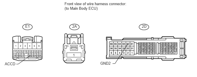
3.CHECK HARNESS AND CONNECTOR (MAIN BODY ECU - BATTERY AND BODY GROUND)
0.918,0.873 1.293,1.106
0.375,0.233
10
E1
2.628,0.873 3.003,1.106
0.375,0.233
10
2A
5.158,0.873 5.533,1.106
0.375,0.233
10
2D
2.347,0.048 4.756,0.415
2.408,0.367
10
Front view of wire harness connector: (to Main Body ECU)
0.173,2.241 0.623,2.443
0.450,0.202
10
ACCD
3.648,2.221 4.082,2.423
0.434,0.202
10
GND2
0.593,2.332 0.662,2.332
0.662,2.332 1.1,2.019
false
4.094,2.314 4.181,2.314
4.181,2.314 4.651,1.597
false
a.
Disconnect the E1, 2A and 2D main body ECU connectors.
b.
Measure the voltage and resistance according to the value(s) in the table below.
- Standard Voltage:
Tester Connection Condition Specified Condition 2A-1 - Body ground Always 11 to 14 V
- Standard Resistance:
Tester Connection Condition Specified Condition E1-22 (ACCD) - 2D-45 Always Below 1 Ω 2D-62 (GND2) - Body ground Always Below 1 Ω E1-22 (ACCD) or 2D-45 - Body ground Always 10 kΩ or higher
OK
REPLACE MAIN BODY ECU
NG
REPAIR OR REPLACE HARNESS OR CONNECTOR