Home › Vehicle Interior › THEFT DETERRENT / KEYLESS ENTRY › ENGINE IMMOBILISER SYSTEM (w/ Entry and Start System) › 2014.08–2015.08
RM2660E _58 Vehicle Interior _052839 THEFT DETERRENT / KEYLESS ENTRY _0255573 ENGINE IMMOBILISER SYSTEM(w/ Entry and Start System) C

THEFT DETERRENT / KEYLESS ENTRY  ENGINE IMMOBILISER SYSTEM(w/ Entry and Start System)  B278A  Short to GND in Immobiliser System Power Source Circuit  


DESCRIPTION

This DTC is output when the engine switch power source supply line is open or shorted.

DTC Code DTC Detection Condition Trouble Area
B278A The engine switch power source supply line is open or shorted.
·

Harness or connector


·

Engine switch


·

Certification ECU (Smart key ECU)


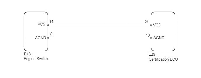
WIRING DIAGRAM

B153714E57
0.854,1.854 1.26,2.052 0.406,0.198 10 false E18 1.344,0.781 1.823,1.031 0.479,0.25 10 false VC5 1.25,1.271 1.698,1.646 0.448,0.375 10 false AGND 1.75,0.688 2,0.875 0.25,0.188 10 false 14 1.792,1.135 1.969,1.313 0.177,0.177 10 false 8 5.177,0.688 5.427,0.875 0.25,0.188 10 false 30 5.188,1.177 5.438,1.354 0.25,0.177 10 false 40 5.469,1.271 5.917,1.646 0.448,0.375 10 false AGND 5.292,1.865 5.781,2.052 0.49,0.188 10 false E29 5.458,0.813 5.75,1.188 0.292,0.375 10 false VC5 0.844,2.021 1.896,2.552 1.052,0.531 10 false Engine Switch 5.302,2.042 6.396,2.219 1.094,0.177 10 false Certification ECU

PROCEDURE

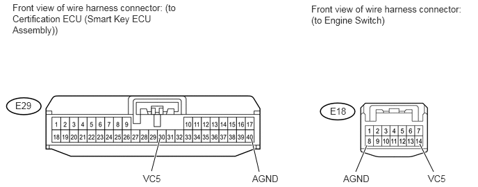
1.CHECK HARNESS AND CONNECTOR (CERTIFICATION ECU (SMART KEY ECU ASSEMBLY) - ENGINE SWITCH)
U163848E02
2.396,2.083 2.271,2.563 true 3.771,2.083 3.885,2.573 true 5.5,2.177 5.333,2.573 true 6.292,2.156 6.5,2.573 true 2.146,2.594 2.49,2.792 0.344,0.198 10 false VC5 3.781,2.594 4.281,2.792 0.5,0.198 10 false AGND 6.417,2.594 6.76,2.792 0.344,0.198 10 false VC5 5.146,2.594 5.646,2.792 0.5,0.198 10 false AGND 0.188,0.031 2.667,0.854 2.479,0.823 10 false Front view of wire harness connector: (to Certification ECU (Smart Key ECU Assembly)) 4.667,0.052 7.021,0.396 2.354,0.344 10 false Front view of wire harness connector: (to Engine Switch) 0.229,1.5 0.552,1.698 0.323,0.198 10 false E29 4.948,1.583 5.26,1.781 0.313,0.198 10 false E18

a.

Disconnect the E29 ECU connector.


b.

Disconnect the E18 switch connector.


c.

Measure the resistance according to the value(s) in the table below.

Standard Resistance:
Tester Connection Condition Specified Condition
E29-30 (VC5) - E18-14 (VC5) Always Below 1 Ω
E29-40 (AGND) - E18-8 (AGND)
E29-30 (VC5) or E18-14 (VC5) - Body ground Always 10 kΩ or higher
E29-40 (AGND) or E18-8 (AGND) - Body ground


OK

2.REPLACE ENGINE SWITCH

NG

REPAIR OR REPLACE HARNESS OR CONNECTOR

2.REPLACE ENGINE SWITCH
a.

for 1GR-FE

i.

Temporarily replace the engine switch with a new one (See page Engine / Hybrid System>1GR-FE (STARTING)>ENGINE SWITCH>REMOVAL).


b.

for 1UR-FE

i.

Temporarily replace the engine switch with a new one (See page Engine / Hybrid System>1UR-FE (STARTING)>ENGINE SWITCH>REMOVAL).


c.

for 1VD-FTV

i.

Temporarily replace the engine switch with a new one (See page Engine / Hybrid System>1VD-FTV (STARTING)>ENGINE SWITCH>REMOVAL).


d.

for 3UR-FE

i.

Temporarily replace the engine switch with a new one (See page Engine / Hybrid System>3UR-FE (STARTING)>ENGINE SWITCH>REMOVAL).


NEXT

3.CLEAR DTC
4.CHECK FOR DTC

OK

END (ENGINE SWITCH IS DEFECTIVE)

NG

REPLACE CERTIFICATION ECU (SMART KEY ECU ASSEMBLY)