RM2660E
_58
Vehicle Interior
_052845
SEAT
_0255625
FRONT POWER SEAT CONTROL SYSTEM(w/ Seat Position Memory System)
J
SEAT FRONT POWER SEAT CONTROL SYSTEM(w/ Seat Position Memory System) Front Power Seat does not Operate with Front Power Seat Switch
DESCRIPTION
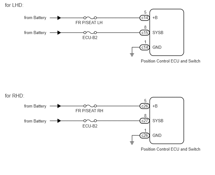
When a signal is input into the position control ECU, the ECU manages the signals received from the front power seat switch LH, and operates each motor. When 2 or more signals are input, the motors only operate when the signals are from the slide switch and reclining switch.
WIRING DIAGRAM
2.519,0.663 3.546,0.820
1.027,0.157
10
FR P/SEAT LH
4.696,1.945 6.792,2.105
2.095,0.160
10
Position Control ECU and Switch
4.805,0.324 4.905,0.474
0.100,0.150
10
5
5.081,0.499 5.288,0.653
0.207,0.153
10
+B
0.807,0.499 1.595,0.688
0.788,0.189
10
from Battery
4.715,0.499 4.972,0.653
0.257,0.153
10
c14
4.806,0.822 4.906,0.971
0.100,0.150
10
8
5.083,0.997 5.483,1.150
0.400,0.153
10
SYSB
4.717,0.997 4.974,1.150
0.257,0.153
10
c15
4.805,1.312 4.905,1.462
0.100,0.150
10
1
5.081,1.487 5.433,1.640
0.352,0.153
10
GND
4.715,1.487 4.972,1.640
0.257,0.153
10
c14
2.75,1.166 3.320,1.322
0.570,0.157
10
ECU-B2
0.807,1 1.595,1.188
0.788,0.189
10
from Battery
2.519,3.608 3.546,3.765
1.027,0.157
10
FR P/SEAT RH
4.696,4.889 6.792,5.050
2.095,0.160
10
Position Control ECU and Switch
4.805,3.269 4.905,3.418
0.100,0.150
10
5
5.081,3.444 5.288,3.597
0.207,0.153
10
+B
0.807,3.443 1.595,3.632
0.788,0.189
10
from Battery
4.715,3.444 4.972,3.597
0.257,0.153
10
c26
4.806,3.766 4.906,3.916
0.100,0.150
10
8
5.083,3.941 5.483,4.094
0.400,0.153
10
SYSB
4.717,3.941 4.974,4.094
0.257,0.153
10
c27
4.805,4.256 4.905,4.406
0.100,0.150
10
1
5.081,4.432 5.433,4.585
0.352,0.153
10
GND
4.715,4.432 4.972,4.585
0.257,0.153
10
c26
2.75,4.11 3.320,4.267
0.570,0.157
10
ECU-B2
0.807,3.944 1.595,4.133
0.788,0.189
10
from Battery
0.164,0.066 0.889,0.305
0.725,0.239
12
for LHD:
0.164,3.082 0.889,3.321
0.725,0.239
12
for RHD:
PROCEDURE
1.INSPECT FUSE (FR P/SEAT LH, FR P/SEAT RH, ECU-B2)
a.
Remove the FR P/SEAT LH*1, FR P/SEAT RH*2 and ECU-B2 fuses from the main body ECU.
- HINT:
-
*1: for LHD
-
*2: for RHD
b.
Measure the resistance according to the value(s) in the table below.
- Standard Resistance:
for LHD Tester Connection Condition Specified Condition FR P/SEAT LH fuse Always Below 1 Ω ECU-B2 fuse Always Below 1 Ω
for RHD Tester Connection Condition Specified Condition FR P/SEAT RH fuse Always Below 1 Ω ECU-B2 fuse Always Below 1 Ω
OK
2.CHECK HARNESS AND CONNECTOR (POSITION CONTROL ECU AND SWITCH - BATTERY AND BODY GROUND)
NG
REPLACE FUSE
2.CHECK HARNESS AND CONNECTOR (POSITION CONTROL ECU AND SWITCH - BATTERY AND BODY GROUND)
1.271,1.542 0.865,2.01
true
1.344,1.813 1.646,2.229
true
2.188,3.552 2.49,3.885
true
0.448,0.021 3.271,0.51
2.823,0.49
10
false
Front view of wire harness connector: (to Position Control ECU and Switch)
0.49,1.219 0.813,1.396
0.323,0.177
10
false
c14
0.49,1.563 0.813,1.74
0.323,0.177
10
false
c14
0.76,1.094 1.083,1.271
0.323,0.177
10
false
*1
0.771,1.438 1.094,1.615
0.323,0.177
10
false
*2
0.531,2 0.865,2.177
0.333,0.177
10
false
GND
1.667,2.167 2,2.344
0.333,0.177
10
false
+B
0.646,2.979 0.969,3.156
0.323,0.177
10
false
c15
0.635,3.333 0.958,3.51
0.323,0.177
10
false
c27
0.958,2.906 1.281,3.083
0.323,0.177
10
false
*1
0.969,3.281 1.292,3.458
0.323,0.177
10
false
*2
2.5,3.875 2.969,4.094
0.469,0.219
10
false
SYSB
0.25,3.938 1.031,4.125
0.781,0.188
10
false
*1: for LHD
0.26,4.229 1.042,4.417
0.781,0.188
10
false
*2: for RHD
a.
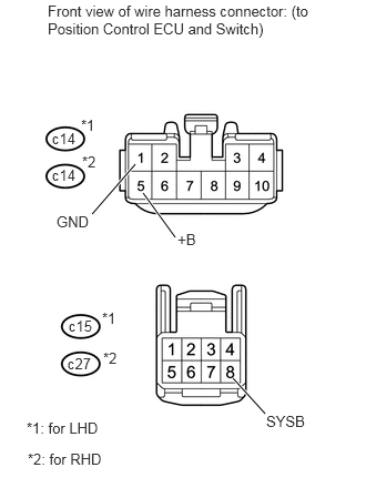
Disconnect the c14*1, c15*1 or c26*2, c27*2 switch connectors.
- HINT:
-
*1: for LHD
-
*2: for RHD
b.
Measure the voltage according to the value(s) in the table below.
- Standard Voltage:
for LHD Tester Connection Condition Specified Condition c14-5 (+B) - Body ground Always 11 to 14 V c15-8 (SYSB) - Body ground Always 11 to 14 V
for RHD Tester Connection Condition Specified Condition c26-5 (+B) - Body ground Always 11 to 14 V c27-8 (SYSB) - Body ground Always 11 to 14 V
c.
Measure the resistance according to the value(s) in the table below.
- Standard Resistance:
for LHD Tester Connection Condition Specified Condition c14-1 (GND) - Body ground Always Below 1 Ω
for RHD Tester Connection Condition Specified Condition c26-1 (GND) - Body ground Always Below 1 Ω
OK
REPLACE POSITION CONTROL ECU AND SWITCH
NG
REPAIR OR REPLACE HARNESS OR CONNECTOR