RM2660E
_58
Vehicle Interior
_052845
SEAT
_0255627
SEAT HEATER SYSTEM
G
SEAT SEAT HEATER SYSTEM ON-VEHICLE INSPECTION
PROCEDURE

 87501B
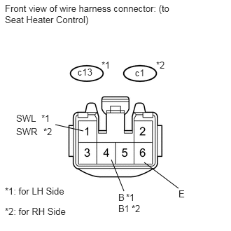
1.INSPECT SEAT HEATER CONTROL SUB-ASSEMBLY (for Front Side)
2.146,2.417 2.656,2.802
false
0.823,1.854 1.24,1.948
false
1.844,2.844 1.656,2.375
false
1.156,0.99 1.427,1.177
0.271,0.188
10
false
c13
0.073,0.042 2.542,0.417
2.469,0.375
10
false
Front view of wire harness connector: (to Seat Heater Control)
0.24,1.677 0.594,1.844
0.354,0.167
10
false
SWL
2.656,2.802 2.781,2.99
0.125,0.188
10
false
E
1.76,2.854 1.885,3.021
0.125,0.167
10
false
B
2.01,1 2.281,1.188
0.271,0.188
10
false
c1
1.51,0.885 1.698,1.031
0.188,0.146
10
false
*1
2.323,0.885 2.51,1.031
0.188,0.146
10
false
*2
0.615,1.677 0.802,1.823
0.188,0.146
10
false
*1
0.24,1.875 0.594,2.042
0.354,0.167
10
false
SWR
0.646,1.875 0.833,2.021
0.188,0.146
10
false
*2
0.073,2.76 1.073,2.927
1,0.167
10
false
*1: for LH Side
0.073,3.063 1.073,3.208
1,0.146
10
false
*2: for RH Side
1.875,2.854 2.063,3
0.188,0.146
10
false
*1
1.76,3.021 1.99,3.188
0.229,0.167
10
false
B1
1.958,3.021 2.146,3.167
0.188,0.146
10
false
*2
a.
Disconnect the c13 and c1 heater control connectors.
b.
Measure the resistance according to the value(s) in the table below.
- Standard Resistance:
for LH Side Tester Connection Specified Condition c13-6 (E) - Body ground Below 1 Ω
for RH Side Tester Connection Specified Condition c1-6 (E) - Body ground Below 1 Ω
If the result is not as specified, there may be a malfunction on the wire harness side.
c.
Measure the voltage according to the value(s) in the table below.
- Standard Voltage:
for LH Side Tester Connection Switch Condition Specified Condition c13-1 (SWL) - c13-6 (E) Engine switch on (IG), seat heater switch off Below 1 V Engine switch on (IG), seat heater switch on 11 to 14 V c13-4 (B) - c13-6 (E) Engine switch off Below 1 V Engine switch on (IG) 11 to 14 V
for RH Side Tester Connection Switch Condition Specified Condition c1-1 (SWR) - c1-6 (E) Engine switch on (IG), seat heater switch off Below 1 V Engine switch on (IG), seat heater switch on 11 to 14 V c1-4 (B1) - c1-6 (E) Engine switch off Below 1 V Engine switch on (IG) 11 to 14 V
If the result is not as specified, there may be a malfunction on the wire harness side.
d.
Connect the c13 and c1 heater control connectors.
e.
1.708,2.792 2.094,3.74
true
1.271,1.677 1.542,1.865
0.271,0.188
10
false
c13
1.917,3.76 2.271,3.927
0.354,0.167
10
false
THL
2.115,1.688 2.385,1.875
0.271,0.188
10
false
c1
1.615,1.604 1.802,1.75
0.188,0.146
10
false
*1
2.448,1.604 2.635,1.75
0.188,0.146
10
false
*2
2.25,3.76 2.438,3.906
0.188,0.146
10
false
*1
1.896,3.958 2.25,4.125
0.354,0.167
10
false
THR
2.281,3.958 2.469,4.104
0.188,0.146
10
false
*2
0.146,4 1.146,4.167
1,0.167
10
false
*1: for LH Side
0.146,4.281 1.146,4.427
1,0.146
10
false
*2: for RH Side
0.146,0.385 2.469,0.771
2.323,0.385
10
false
Component with harness connector: (Seat Heater Control)
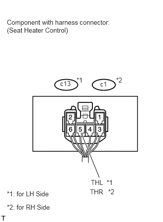
Measure the voltage according to the value(s) in the table below.
- Standard Voltage:
for LH Side Tester Connection Switch Condition Specified Condition c13-5 (THL) - Body ground Engine switch on (IG), seat heater switch on, volume Min→ Max Gradual increase from below 1 V to 11 to 14 V
for RH Side Tester Connection Switch Condition Specified Condition c1-5 (THR) - Body ground Engine switch on (IG), seat heater switch on, volume Min → Max Gradual increase from below 1 V to 11 to 14 V
If the result is not as specified, the seat heater control may have a malfunction.