SEAT CLIMATE CONTROL SEAT SWITCH INSPECTION
PROCEDURE

 84751
1.INSPECT SEAT HEATER SWITCH (w/ Seat Heater System)
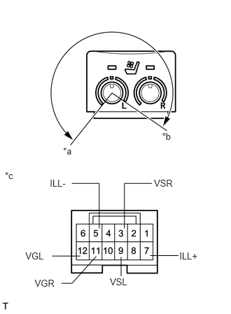
Measure the resistance according to the value(s) in the table below.
- Standard Resistance:
- for LH Side:
Tester Connection Switch Condition Specified Condition 9 (VSL) - 12 (VGL) COLD (HI) to HOT (HI) 6.0 to 0.06 kΩ
- Standard Resistance:
- for RH Side:
Tester Connection Switch Condition Specified Condition 3 (VSR) - 11 (VGR) COLD (HI) to HOT (HI) 6.0 to 0.06 kΩ
- HINT:
-
As the dial is being turned, the resistance changes gradually.
If the result is not as specified, replace the seat heater switch.
| *a | COLD (HI) |
| *b | HOT (HI) |
| *c | Component without harness connected
(Seat Heater Switch) |
If the result is not as specified, replace the seat heater switch.
Apply battery voltage to the switch connector, and check that the seat heater switch illuminates.
- OK:
Measurement Condition Specified Condition Battery positive (+) → 7 (ILL+)
Battery negative (-) → 5 (ILL-)Illuminates
If the result is not as specified, replace the seat heater switch.
84751
2.INSPECT SEAT HEATER SWITCH (w/o Seat Heater System)
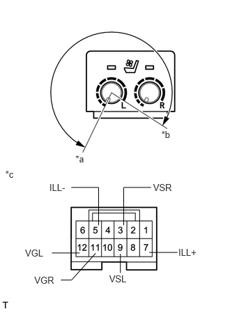
Measure the resistance according to the value(s) in the table below.
- Standard Resistance:
- for LH Side:
Tester Connection Switch Condition Specified Condition 9 (VSL) - 12 (VGL) ON (MIN) to ON (MAX) 6.0 to 0.06 kΩ
- Standard Resistance:
- for RH Side:
Tester Connection Switch Condition Specified Condition 3 (VSR) - 11 (VGR) ON (MIN) to ON (MAX) 6.0 to 0.06 kΩ
- HINT:
-
As the dial is being turned, the resistance changes gradually.
If the result is not as specified, replace the seat heater switch.
| *a | ON (MIN) |
| *b | ON (MAX) |
| *c | Component without harness connected
(Seat Heater Switch) |
Apply battery voltage to the switch connector, and check that the seat heater switch illuminates.
- OK:
Measurement Condition Specified Condition Battery positive (+) → 8 (ILL+)
Battery negative (-) → 5 (ILL-)Illuminates
If the result is not as specified, replace the seat heater switch.