RM2660E
_58
Vehicle Interior
_052848
POWER OUTLETS (INT)
_0255713
VOLTAGE INVERTER
G
POWER OUTLETS (INT) VOLTAGE INVERTER ON-VEHICLE INSPECTION
PROCEDURE

 1.INSPECT VOLTAGE INVERTER
- HINT:
-
Remove interior parts so that the voltage inverter can be seen.
a.
1.048,2.424 1.048,2.946
1.048,2.946 1.423,2.946
false
1.062,1.909 1.062,1.251
1.062,1.251 0.655,1.251
false
1.486,2.866 1.684,3.022
0.198,0.156
10
IG
0.22,1.182 0.566,1.338
0.346,0.156
10
GND
0.401,0.205 0.598,0.361
0.198,0.156
10
*a
2.732,2.077 2.996,2.258
0.264,0.181
10
K44
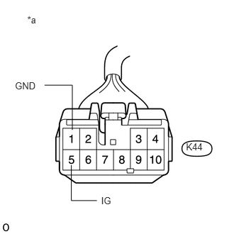
Disconnect the voltage inverter connector.
b.
Measure the voltage according to the value(s) in the table below.
- Standard Voltage:
Tester Connection Switch Condition Specified Condition K44-5 (IG) - K44-1 (GND) Ignition switch on (IG) 10 to 16 V K44-1 (GND) - Body ground Always Below 1 V
If the result is not as specified, repair or replace the harness or connector.
| *a | Front view of wire harness connector:
(to Voltage Inverter) |
c.
1.631,1.997 1.631,1.395
1.631,1.395 1.927,1.395
false
0.478,1.252 0.773,1.408
0.295,0.156
10
AC1
1.967,1.321 2.262,1.477
0.295,0.156
10
AC2
1.297,1.796 1.297,1.332
1.297,1.332 0.845,1.332
false
0.263,0.238 0.433,0.394
0.170,0.156
10
*a
1.578,0.709 1.842,0.890
0.264,0.181
10
K44
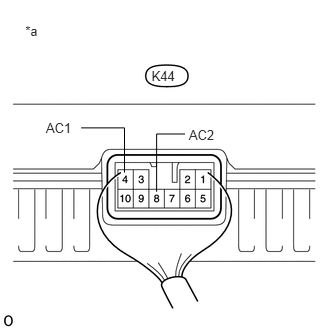
Reconnect the voltage inverter connector.
d.
Measure the voltage according to the value(s) in the table below.
- Standard Voltage:
Tester Connection Switch Condition Specified Condition K44-4 (AC1) - K44-8 (AC2) Ignition switch on (IG)
Main switch onAC 198 to 242 V
If the result is not as specified, replace the voltage inverter.
| *a | Component with harness connected:
(Voltage Inverter) |