INTERIOR PANELS / TRIM FRONT CONSOLE BOX(w/ Cool Box) REASSEMBLY
CAUTION / NOTICE / HINT
- HINT:
- ·
Use the same procedures for LHD and RHD vehicles.
·The procedures listed below are for LHD vehicles.
PROCEDURE

 88501D
1.INSTALL NO. 2 COOLER EVAPORATOR SUB-ASSEMBLY
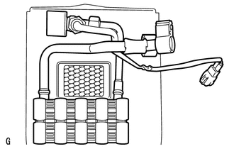
Install the evaporator.
88306
2.INSTALL NO. 1 COOLER BLOWER MOTOR SUB-ASSEMBLY
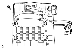
Attach the 4 claws to install the blower motor.
Install the 2 screws.
88625B
3.INSTALL NO. 3 COOLER THERMISTOR
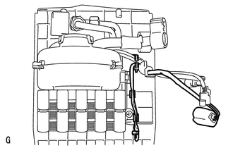
Install the thermistor.
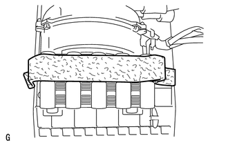
Install a new cool box insulator, as shown in the illustration.
4.INSTALL UPPER COOLING UNIT CASE
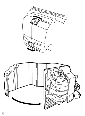
Attach the 2 hooks and close the case, as shown in the illustration.
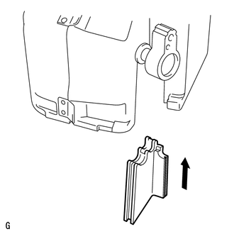
Install the cooling unit case.
5.INSTALL LOWER COOLING UNIT CASE SUB-ASSEMBLY
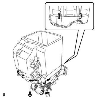
Install the lower cooling unit case with the 4 holding springs.
Connect the 3 connectors.
Install the screw.
88721C
6.INSTALL LIQUID HOSE
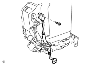
Sufficiently apply compressor oil to a new O-ring and the fitting surface of the cooler evaporator.
- Compressor oil:
ND-OIL 8 or equivalent
Install the O-ring on the liquid hose.
Install the liquid hose to the evaporator with the bolt.
- Torque:
- 5.4 N*m (55 kgf*cm, 48 in.*lbf)
88502
7.INSTALL COOLING UNIT CASE SUB-ASSEMBLY
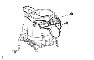
Install the air duct to the case with the 2 screws.
58888C
8.INSTALL COOLING BOX BASE
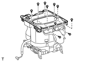
Install the cooling box base with the 10 screws.
58889C
9.INSTALL COOLING BOX BRACKET
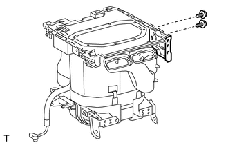
Install the bracket with the 2 screws.
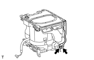
Install the mounting bracket with the 2 screws.
58899B
10.INSTALL NO. 2 COOLING BOX BRACKET
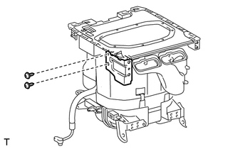
Install the bracket with the 2 screws.
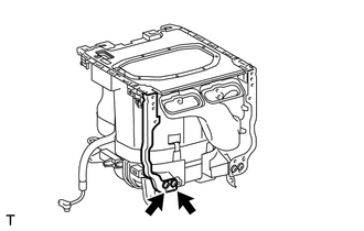
Install the mounting bracket with the 2 screws.
88601
11.INSTALL COOLER CONTROL SWITCH SUB-ASSEMBLY
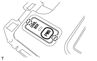
Connect the connector.
Attach the 2 claws to install the switch.
88650E
12.INSTALL AIR CONDITIONING AMPLIFIER ASSEMBLY
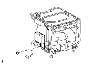
Install the amplifier with the screw.
Connect the connector.
13.INSTALL COOLING BOX ASSEMBLY
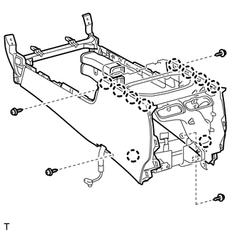
Attach the 10 claws to install the cooling box.
Install the 4 screws.
58971
14.INSTALL CONSOLE COMPARTMENT DOOR LOCK
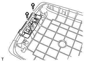
Install the door lock with the 2 screws.
58907
15.INSTALL CONSOLE COMPARTMENT DOOR HINGE SUB-ASSEMBLY
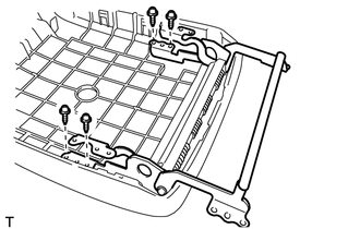
Install the door hinge with the 4 screws.
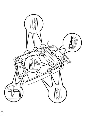
Attach the 12 claws to install the inner door.
58908A
16.INSTALL CONSOLE COMPARTMENT DOOR LOCK SUB-ASSEMBLY
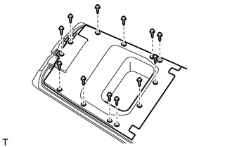
Install the door lock. Then install the lower box with the 12 screws.
58905
17.INSTALL CONSOLE COMPARTMENT DOOR SUB-ASSEMBLY
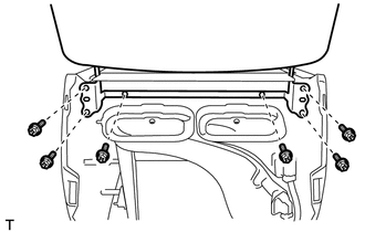
Install the door with the 6 screws.
58993
18.INSTALL REAR CONSOLE BOX MOUNTING BRACKET
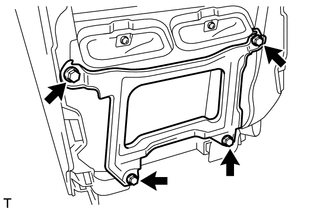
Install the bracket with the 4 bolts.
- Torque:
- 8.5 N*m (87 kgf*cm, 75 in.*lbf)
55548B
19.INSTALL INSTRUMENT PANEL HOLE COVER
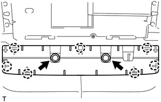
Attach the 7 claws to install the hole cover.
Install the 2 screws.
55549C
20.INSTALL REAR COOLER SWITCH HOLE COVER (w/o Rear Cooler)
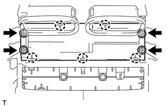
Attach the 5 claws.
Install the hole cover with the 4 screws.
55900
21.INSTALL AIR CONDITIONING CONTROL ASSEMBLY (w/ Rear Cooler)
55900D
22.INSTALL NO. 2 AIR CONDITIONING CONTROL ASSEMBLY (w/ Rear Air Conditioning System)