WINDOW / GLASS POWER WINDOW CONTROL SYSTEM(for Models with Jam Protection Function on Driver Door Window Only) Remote Up / Down Function does not Operate
DESCRIPTION
When the ignition switch is ON and window lock switch is off, the multiplex network master switch sends remote up/down signals to each power window regulator motor.
WIRING DIAGRAM
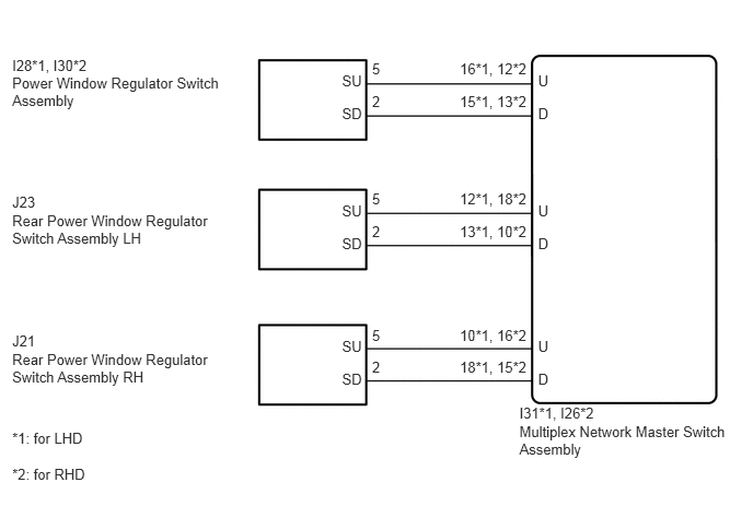
PROCEDURE
Turn the window lock switch off and operate the switches on the multiplex network master switch. Check that the remote up/down function operates (See page Vehicle Exterior>WINDOW / GLASS>POWER WINDOW CONTROL SYSTEM(for Models with Jam Protection Function on Driver Door Window Only)>OPERATION CHECK).
- OK:
Remote up/down function operates.
OK
NG
Check that the front passenger side power window and rear power window manual up/down function operates normally.
- OK:
Manual up/down function operates normally.
OK
NG
*1: for LHD
*2: for RHD
Disconnect the I31*1 or I26*2 multiplex network master switch assembly connector.
Disconnect the I28*1 or I30*2 power window regulator switch assembly connector.
Measure the resistance according to the value(s) in the table below.
- Standard Resistance:
for LHD Tester Connection Condition Specified Condition I31-16 (U) - I28-5 (SU) Always Below 1 Ω I31-15 (D) - I28-2 (SD) Always Below 1 Ω I31-16 (U) or I28-5 (SU) - Body ground Always 10 kΩ or higher I31-15 (D) or I28-2 (SD) - Body ground Always 10 kΩ or higher
for RHD Tester Connection Condition Specified Condition I26-12 (U) - I30-5 (SU) Always Below 1 Ω I26-13 (D) - I30-2 (SD) Always Below 1 Ω I26-12 (U) or I30-5 (SU) - Body ground Always 10 kΩ or higher I26-13 (D) or I30-2 (SD) - Body ground Always 10 kΩ or higher
OK
NG
Disconnect the I31*1 or I26*2 multiplex network master switch assembly connector.
*1: for LHD
*2: for RHD
Disconnect the J23 rear power window regulator switch assembly LH connector.
Measure the resistance according to the value(s) in the table below.
- Standard Resistance:
for LHD Tester Connection Condition Specified Condition I31-12 (U) - J23-5 (SU) Always Below 1 Ω I31-13 (D) - J23-2 (SD) Always Below 1 Ω I31-12 (U) or J23-5 (SU) - Body ground Always 10 kΩ or higher I31-13 (D) or J23-2 (SD) - Body ground Always 10 kΩ or higher
for RHD Tester Connection Condition Specified Condition I26-18 (U) - J23-5 (SU) Always Below 1 Ω I26-10 (D) - J23-2 (SD) Always Below 1 Ω I26-18 (U) or J23-5 (SU) - Body ground Always 10 kΩ or higher I26-10 (D) or J23-2 (SD) - Body ground Always 10 kΩ or higher
OK
NG
Disconnect the I31*1 or I26*2 multiplex network master switch assembly connector.
*1: for LHD
*2: for RHD
Disconnect the J21 rear power window regulator switch assembly RH connector.
Measure the resistance according to the value(s) in the table below.
- Standard Resistance:
for LHD Tester Connection Condition Specified Condition I31-10 (U) - J21-5 (SU) Always Below 1 Ω I31-18 (D) - J21-2 (SD) Always Below 1 Ω I31-10 (U) or J21-5 (SU) - Body ground Always 10 kΩ or higher I31-18 (D) or J21-2 (SD) - Body ground Always 10 kΩ or higher
for RHD Tester Connection Condition Specified Condition I26-16 (U) - J21-5 (SU) Always Below 1 Ω I26-15 (D) - J21-2 (SD) Always Below 1 Ω I26-16 (U) or J21-5 (SU) - Body ground Always 10 kΩ or higher I26-15 (D) or J21-2 (SD) - Body ground Always 10 kΩ or higher
OK
NG