DOOR / HATCH BACK DOOR ADJUSTMENT
PROCEDURE

 65061
1.INSPECT TAIL GATE PANEL SUB-ASSEMBLY
Check that the clearance measurements of areas H to I are within the standard range.
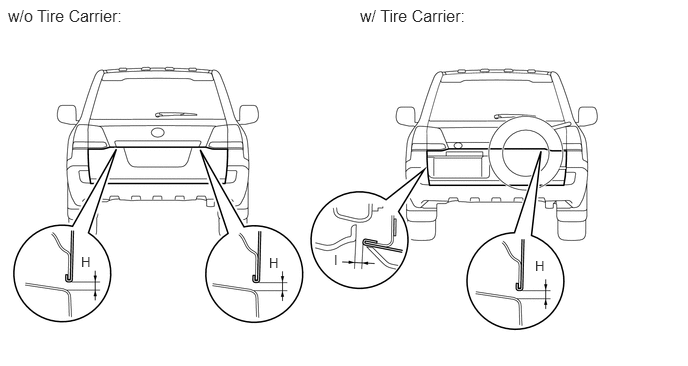
- Standard Measurement:
Area Specified Condition H 3.8 to 6.8 mm (0.150 to 0.268 in.) I 3.5 to 6.5 mm (0.138 to 0.256 in.)
65061
2.ADJUST TAIL GATE PANEL SUB-ASSEMBLY
Loosen the hinge bolts.
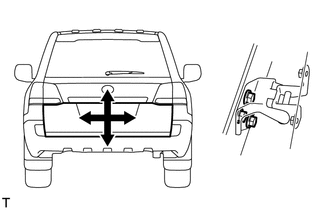
Adjust the tail gate by moving it up and down and left and right so that the dimensions are within the specified range.
Tighten the hinge bolts.
- Torque:
- 28 N*m (286 kgf*cm, 21 ft.*lbf)
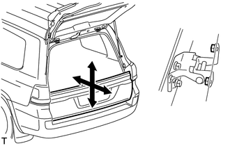
Loosen the hinge bolts.
Adjust the tail gate by moving it up and down and forward and backward so that the dimensions are within the specified range.
Tighten the hinge bolts.
- Torque:
- 31 N*m (316 kgf*cm, 23 ft.*lbf)
69430C
3.ADJUST DOOR LOCK STRIKER
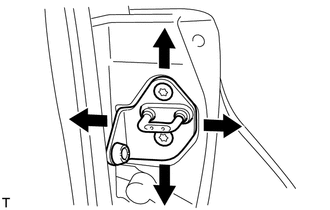
Using a T40 "TORX" socket, adjust the striker position by slightly loosening the striker mounting screws and hitting the striker with a plastic-faced hammer.
Using a T40 "TORX" socket, tighten the striker mounting screws after the adjustment.
- Torque:
- 12 N*m (122 kgf*cm, 9 ft.*lbf)
67005
4.INSPECT BACK DOOR PANEL SUB-ASSEMBLY
Check that the clearance measurements of areas A to G are within the standard range.
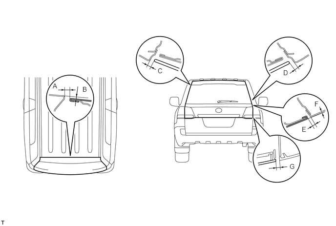
- Standard Measurement:
Area Specified Condition Area Specified Condition A 5.7 to 8.7 mm (0.224 to 0.343 in.) E 2.7 to 5.7 mm (0.106 to 0.224 in.) B 0.0 to 3.0 mm (0.000 to 0.118 in.) F -1.4 to 1.6 mm (-0.0551 to 0.0630 in.) C 3.75 to 6.75 mm (0.148 to 0.266 in.) G 5.0 mm (0.197 in.) D 3.75 to 6.75 mm (0.148 to 0.266 in.) - -
69431A
5.ADJUST REAR SWING GATE LOCK STRIKER
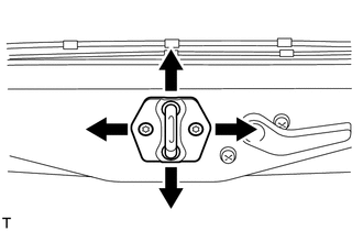
Check that the door fit and door linkages are adjusted correctly.
Using a T40 "TORX" socket, adjust the striker position by slightly loosening the striker mounting screws and hitting the striker with a plastic-faced hammer.
Using a T40 "TORX" socket, tighten the striker mounting screws after the adjustment.
- Torque:
- 23 N*m (235 kgf*cm, 17 ft.*lbf)
67005
6.ADJUST BACK DOOR PANEL SUB-ASSEMBLY
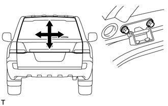
Loosen the hinge bolts.
Adjust the back door by moving it up and down and left and right so that the dimensions are within the specified range.
Tighten the hinge bolts.
- Torque:
- 19 N*m (194 kgf*cm, 14 ft.*lbf)
Partially remove the roof headlining.
w/ Sliding Roof:
(See page Vehicle Interior>SEAT BELT>REAR CENTER SEAT OUTER BELT ASSEMBLY(for Rear No. 2 Seat)>REMOVAL)
w/o Sliding Roof:
(See page Vehicle Interior>SEAT BELT>REAR CENTER SEAT OUTER BELT ASSEMBLY(for Rear No. 2 Seat)>REMOVAL)
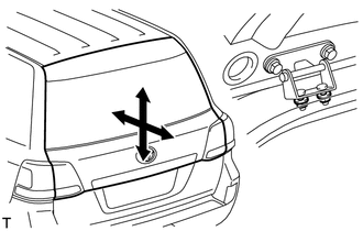
Loosen the hinge nuts.
Adjust the back door by moving it up and down and forward and backward so that the dimensions are within the specified range.
Tighten the hinge nuts.
- Torque:
- 19 N*m (194 kgf*cm, 14 ft.*lbf)
Install the roof headlining.
w/ Sliding Roof:
(See page Vehicle Interior>SEAT BELT>REAR CENTER SEAT OUTER BELT ASSEMBLY(for Rear No. 2 Seat)>INSTALLATION)
w/o Sliding Roof:
(See page Vehicle Interior>SEAT BELT>REAR CENTER SEAT OUTER BELT ASSEMBLY(for Rear No. 2 Seat)>INSTALLATION)