DOOR / HATCH BACK DOOR(for Double Swing Out Type) ADJUSTMENT
CAUTION / NOTICE / HINT
- NOTICE:
- ·
A bolt without a torque specification is shown in the standard bolt chart (See page General>SPECIFICATIONS>STANDARD BOLT>SPECIFIED TORQUE FOR STANDARD BOLTS).
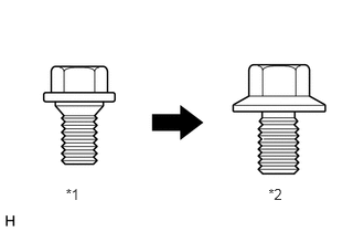
·Centering bolts are used to mount the door hinge to the vehicle body and door. The door cannot be adjusted with the centering bolts on. Substitute the centering bolts for standard bolts when making adjustments.
| *1 | Centering Bolt |
| *2 | Standard Bolt |
PROCEDURE

 67005D
1.INSPECT BACK DOOR PANEL SUB-ASSEMBLY RH (for RH Side)
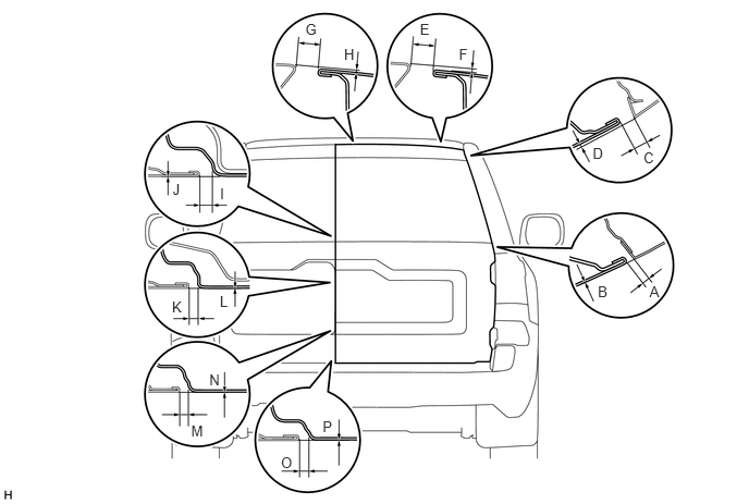
Check that the clearance measurements of areas A to P are within the standard ranges.
- Standard:
Area Specified Condition Area Specified Condition A 4.6 to 8.6 mm (0.181 to 0.339 in.) B -2 to 2 mm (-0.0787 to 0.0787 in.) C 6.0 to 10.0 mm (0.236 to 0.394 in.) D -0.9 to 3.1 mm (-0.0354 to 0.122 in.) E 11.3 to 14.3 mm (0.445 to 0.563 in.) F 0.5 to 3.5 mm (0.0197 to 0.138 in.) G 11.3 to 14.3 mm (0.445 to 0.563 in.) H 0 to 3.0 mm (0 to 0.118 in.) I 3.5 to 7.5 mm (0.138 to 0.295 in.) J -2 to 2 mm (-0.0787 to 0.0787 in.) K 3.5 to 7.5 mm (0.138 to 0.295 in.) L -2 to 2 mm (-0.0787 to 0.0787 in.) M 3.5 to 7.5 mm (0.138 to 0.295 in.) N -1.8 to 2.2 mm (-0.0709 to 0.0866 in.) O 3.5 to 7.5 mm (0.138 to 0.295 in.) P -2 to 2 mm (-0.0787 to 0.0787 in.)
69455A
2.REMOVE BACK DOOR UPPER LOCK STRIKER COVER (for RH Side)
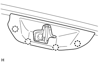
Detach the 4 claws and remove the back door upper lock striker cover.
67005D
3.ADJUST BACK DOOR PANEL SUB-ASSEMBLY RH (for RH Side)
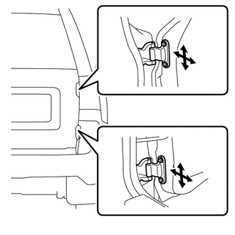
Loosen the hinge bolts on the back door panel and adjust the back door panel position.
Tighten the hinge bolts on the back door panel after the adjustment.
- Torque:
- 31 N*m (316 kgf*cm, 23 ft.*lbf)
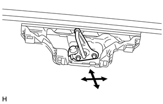
Adjust the back door lock striker position by slightly loosening the bolts and hitting the back door lock striker with a plastic-faced hammer.
Tighten the bolts after the adjustment.
- Torque:
- 29 N*m (296 kgf*cm, 21 ft.*lbf)
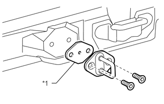
Using a T40 "TORX" socket wrench, remove the 2 bolts and striker.
Select a back door lock striker shim so that the clearance measurements are within the specified range.
- HINT:
-
There are 2 types of back door lock striker shims (0.5 mm and 2.0 mm).
| *1 | Back Door Lock Striker Shim |
Using a T40 "TORX" socket wrench, install the striker with the 2 bolts.
- HINT:
-
Mark sure that the yellow marking is facing up when installing the striker.
- Torque:
- 23 N*m (235 kgf*cm, 17 ft.*lbf)
69455A
4.INSTALL BACK DOOR UPPER LOCK STRIKER COVER (for RH Side)
Attach the 4 claws to install the back door upper lock striker cover.
67006A
5.INSPECT BACK DOOR PANEL SUB-ASSEMBLY LH (for LH Side)
Check that the clearance measurements of areas A to P are within the standard ranges.
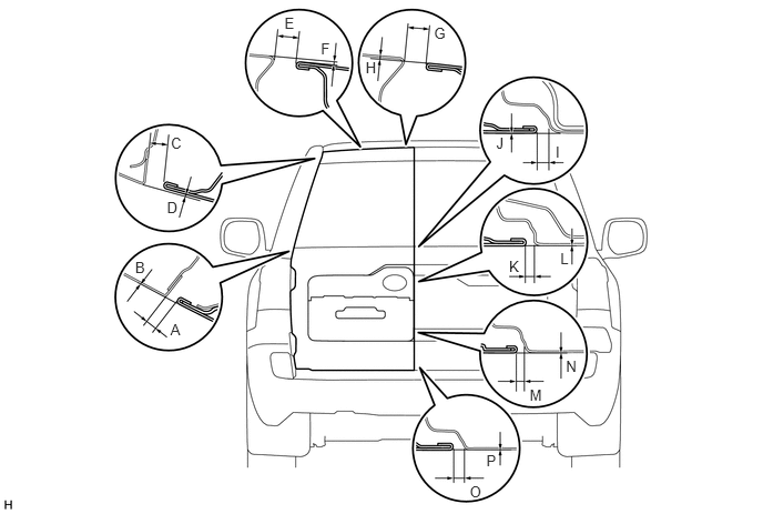
- Standard:
Area Specified Condition Area Specified Condition A 4.6 to 8.6 mm (0.181 to 0.339 in.) B -2 to 2 mm (-0.0787 to 0.0787 in.) C 6.0 to 10.0 mm (0.236 to 0.394 in.) D -0.9 to 3.1 mm (-0.0354 to 0.122 in.) E 11.3 to 14.3 mm (0.445 to 0.563 in.) F 0.3 to 3.3 mm (0.0118 to 0.130 in.) G 11.3 to 14.3 mm (0.445 to 0.563 in.) H 0 to 3.0 mm (0 to 0.118 in.) I 3.5 to 7.5 mm (0.138 to 0.295 in.) J -2 to 2 mm (-0.0787 to 0.0787 in.) K 3.5 to 7.5 mm (0.138 to 0.295 in.) L -2 to 2 mm (-0.0787 to 0.0787 in.) M 3.5 to 7.5 mm (0.138 to 0.295 in.) N -1.8 to 2.2 mm (-0.0709 to 0.0866 in.) O 3.5 to 7.5 mm (0.138 to 0.295 in.) P -2 to 2 mm (-0.0787 to 0.0787 in.)
67006A
6.ADJUST BACK DOOR PANEL SUB-ASSEMBLY LH (for LH Side)
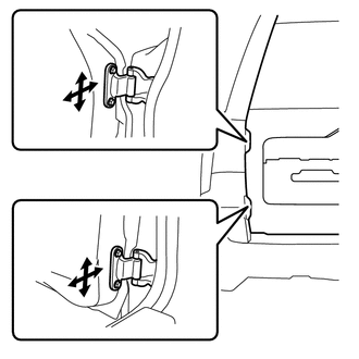
Loosen the hinge bolts on the back door panel and adjust the back door panel position.
Tighten the hinge bolts on the back door panel after the adjustment.
- Torque:
- 31 N*m (316 kgf*cm, 23 ft.*lbf)
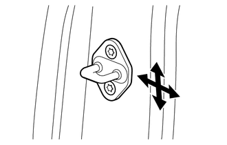
Using a T40 "TORX" socket, adjust the back door lock striker plate position by slightly loosening the bolts and hitting the back door lock striker plate with a plastic-faced hammer.
Using a T40 "TORX" socket, tighten the bolts after the adjustment.
- Torque:
- 23 N*m (235 kgf*cm, 17 ft.*lbf)