DOOR / HATCH BACK DOOR(for Double Swing Out Type) INSTALLATION
CAUTION / NOTICE / HINT
- HINT:
-
A bolt without a torque specification is shown in the standard bolt chart (See page General>SPECIFICATIONS>STANDARD BOLT>SPECIFIED TORQUE FOR STANDARD BOLTS).
PROCEDURE

 51950A
1.INSTALL SPARE WHEEL CARRIER GUIDE ROLLER ASSEMBLY (w/ Tire Carrier)
Apply MP grease to the sliding areas of the spare wheel carrier guide roller and spare wheel carrier.
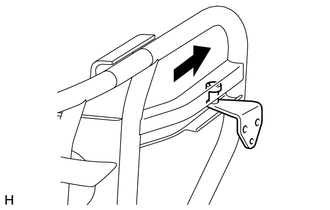
Install the spare wheel carrier guide roller in the direction indicated by the arrow in the illustration.
51948
2.INSTALL SPARE WHEEL CARRIER AUXILIARY STOPPER (w/ Tire Carrier)
- HINT:
-
Use the same procedure for both spare wheel carrier auxiliary stoppers.
Clean the threaded surfaces on the vehicle body with a non-residue solvent.
Apply adhesive to the threads of the bolt.
- Adhesive:
Toyota Genuine Adhesive 1324, Three Bond 1324 or equivalent
Install the spare wheel carrier auxiliary stopper with the 2 bolts.
- Torque:
- 15 N*m (148 kgf*cm, 11 ft.*lbf)
51903B
3.INSTALL SPARE WHEEL CARRIER SUB-ASSEMBLY (w/ Tire Carrier)
Clean the threaded surfaces on the vehicle body with a non-residue solvent.
Apply adhesive to the threads of bolt A and B.
- Adhesive:
Toyota Genuine Adhesive 1324, Three Bond 1324 or equivalent
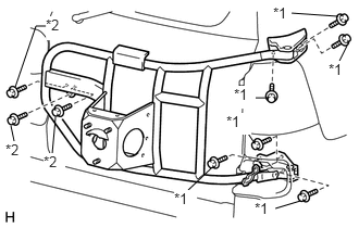
Install the spare wheel carrier with the 9 bolts.
- Torque:
- Bolt A : 29 N*m (196 kgf*cm, 21 ft.*lbf)
- Bolt B : 15 N*m (148 kgf*cm, 11 ft.*lbf)
| *1 | Bolt A |
| *2 | Bolt B |
Install the spare tire with the 3 bolts.
- Torque:
- 90 N*m (918 kgf*cm, 66 ft.*lbf)
51902A
4.INSTALL SPARE WHEEL COVER SUB-ASSEMBLY (w/ Tire Carrier)
Attach the clip to install the spare wheel cover.
Install the 2 nuts.
51937C
5.INSTALL SPARE WHEEL CARRIER HINGE BRACKET (w/ Tire Carrier)
Attach the 2 claws to install the spare wheel carrier hinge bracket.