Home › Vehicle Exterior › MIRROR (EXT) › POWER MIRROR CONTROL SYSTEM(w/ Retract Mirror) › 2014.08–2015.08
RM2660E _59 Vehicle Exterior _052853 MIRROR (EXT) _0255766 POWER MIRROR CONTROL SYSTEM(w/ Retract Mirror) J

MIRROR (EXT)  POWER MIRROR CONTROL SYSTEM(w/ Retract Mirror)  Power Retractable Mirrors do not Operate with Power Retract Mirror Switch  


SYSTEM DESCRIPTION

This circuit detects the conditions of the mirror retract switch.

The outer mirror switch sends information about the operating condition of the mirror retract switch (switch input signals) through the CAN communication line. Then the switch input signals are sent to the outer mirror control ECU.

WIRING DIAGRAM
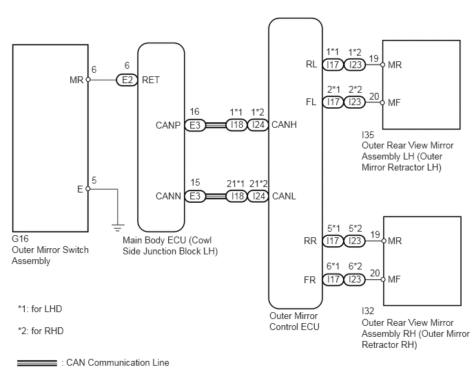
B188307E06
5.469,4.802 7.146,5.458 1.677,0.656 10 false Outer Rear View Mirror Assembly RH (Outer Mirror Retractor RH) 5.469,2.115 7.021,2.771 1.552,0.656 10 false Outer Rear View Mirror Assembly LH (Outer Mirror Retractor LH) 5.469,1.958 5.698,2.125 0.229,0.167 10 false I35 4.073,4.698 4.958,5.052 0.885,0.354 10 false Outer Mirror Control ECU 1.854,3.552 3.375,3.875 1.521,0.323 10 false Main Body ECU (Cowl Side Junction Block LH) 0.177,3.698 1.438,4.042 1.26,0.344 10 false Outer Mirror Switch Assembly 0.927,5.406 2.646,5.594 1.719,0.188 10 false : CAN Communication Line 0.271,4.594 1.01,4.781 0.74,0.188 10 false *1: for LHD 0.271,4.927 1.021,5.115 0.75,0.188 10 false *2: for RHD 5.469,4.625 5.698,4.792 0.229,0.167 10 false I32 0.177,3.531 0.51,3.698 0.333,0.167 10 false G16 5.865,3.563 6.104,3.729 0.24,0.167 10 false MR 5.865,4.146 6.115,4.313 0.25,0.167 10 false MF 4.594,3.563 4.833,3.729 0.24,0.167 10 false RR 4.938,3.563 5.177,3.729 0.24,0.167 10 false I17 4.594,4.156 4.844,4.323 0.25,0.167 10 false FR 4.948,4.146 5.198,4.313 0.25,0.167 10 false I17 5.865,0.896 6.104,1.063 0.24,0.167 10 false MR 5.865,1.469 6.115,1.635 0.25,0.167 10 false MF 4.625,0.885 4.865,1.052 0.24,0.167 10 false RL 4.938,0.896 5.177,1.063 0.24,0.167 10 false I17 4.625,1.458 4.875,1.625 0.25,0.167 10 false FL 4.927,0.698 5.177,0.865 0.25,0.167 10 false 1*1 4.948,1.271 5.219,1.438 0.271,0.167 10 false 2*1 5.573,0.802 5.76,0.969 0.188,0.167 10 false 19 5.583,1.375 5.76,1.542 0.177,0.167 10 false 20 4.948,3.375 5.198,3.542 0.25,0.167 10 false 5*1 4.938,3.948 5.177,4.115 0.24,0.167 10 false 6*1 5.594,3.469 5.781,3.635 0.188,0.167 10 false 19 5.594,4.052 5.771,4.219 0.177,0.167 10 false 20 4.948,1.458 5.198,1.625 0.25,0.167 10 false I17 5.271,3.563 5.51,3.729 0.24,0.167 10 false I23 5.271,4.146 5.521,4.313 0.25,0.167 10 false I23 5.281,0.896 5.521,1.063 0.24,0.167 10 false I23 5.26,0.708 5.51,0.875 0.25,0.167 10 false 1*2 5.271,1.271 5.542,1.438 0.271,0.167 10 false 2*2 5.271,3.375 5.521,3.542 0.25,0.167 10 false 5*2 5.271,3.948 5.51,4.115 0.24,0.167 10 false 6*2 5.271,1.458 5.521,1.625 0.25,0.167 10 false I23 3.49,1.802 3.729,1.969 0.24,0.167 10 false I18 3.5,2.885 3.75,3.052 0.25,0.167 10 false I18 4.104,1.802 4.521,1.969 0.417,0.167 10 false CANH 4.115,2.885 4.521,3.052 0.406,0.167 10 false CANL 2.354,1.813 2.771,1.979 0.417,0.167 10 false CANP 2.146,1.125 2.563,1.292 0.417,0.167 10 false RET 1.052,1.125 1.313,1.292 0.26,0.167 10 false MR 1.167,2.781 1.302,2.948 0.135,0.167 10 false E 1.885,0.906 2,1.073 0.115,0.167 10 false 6 1.385,0.969 1.5,1.135 0.115,0.167 10 false 6 1.385,2.646 1.5,2.813 0.115,0.167 10 false 5 1.844,1.125 2.042,1.292 0.198,0.167 10 false E2 2.354,2.885 2.781,3.052 0.427,0.167 10 false CANN 2.865,1.813 3.104,1.979 0.24,0.167 10 false E3 2.865,2.885 3.115,3.052 0.25,0.167 10 false E3 2.865,1.604 3.052,1.771 0.188,0.167 10 false 16 2.875,2.677 3.073,2.844 0.198,0.167 10 false 15 3.469,1.615 3.719,1.781 0.25,0.167 10 false 1*1 3.427,2.698 3.729,2.865 0.302,0.167 10 false 21*1 3.813,1.802 4.052,1.969 0.24,0.167 10 false I24 3.823,2.885 4.073,3.052 0.25,0.167 10 false I24 3.792,1.615 4.042,1.781 0.25,0.167 10 false 1*2 3.771,2.698 4.073,2.865 0.302,0.167 10 false 21*2

PROCEDURE

1.CHECK DTC
a.

Use the intelligent tester to check if the CAN communication system is functioning normally.

Result
Result Proceed to
CAN DTC is not output A
CAN DTC is output (for LHD) B
CAN DTC is output (for RHD) C


A

2.READ VALUE USING INTELLIGENT TESTER (MIRROR RETRACT SWITCH)

B

C

2.READ VALUE USING INTELLIGENT TESTER (MIRROR RETRACT SWITCH)
a.

Check the Data List for proper functioning of the mirror retract switch (See page Vehicle Exterior>MIRROR (EXT)>POWER MIRROR CONTROL SYSTEM(w/ Retract Mirror)>DATA LIST / ACTIVE TEST).

Main Body
Tester Display Measurement Item/Range Normal Condition Diagnostic Note
Outer Mirror Fold SW Mirror retract switch signal / ON or OFF ON: Switch is on (retracting)
OFF: Switch is off
-

OK:

On tester screen, each item changes between ON and OFF according to above chart.


OK

3.PERFORM ACTIVE TEST USING INTELLIGENT TESTER (MIRROR RETRACT FUNCTION)

NG

4.INSPECT RETRACTABLE OUTER MIRROR SWITCH
3.PERFORM ACTIVE TEST USING INTELLIGENT TESTER (MIRROR RETRACT FUNCTION)
a.

Select the Active Test, use the intelligent tester to generate a control command, and then check the power mirror control function (See page Vehicle Exterior>MIRROR (EXT)>POWER MIRROR CONTROL SYSTEM(w/ Retract Mirror)>DATA LIST / ACTIVE TEST).

Mirror
Tester Display Test Part Control Range Diagnostic Note
Mirror Fold Mirror retract operation FOLD / OFF -
Mirror Return Mirror retract operation RETURN / OFF -

Result
Result Proceed to
Outer rear view mirror operates normally A
Outer rear view mirror LH does not operate normally B
Outer rear view mirror RH does not operate normally C


A

REPLACE OUTER MIRROR CONTROL ECU

B

6.INSPECT OUTER MIRROR RETRACTOR LH

C

8.INSPECT OUTER MIRROR RETRACTOR RH
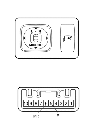
4.INSPECT RETRACTABLE OUTER MIRROR SWITCH
a.
B315167E02
2.049,4.115 2.170,4.278 0.121,0.163 10 E 1.203,4.127 1.463,4.293 0.260,0.166 10 MR 1.665,3.795 1.373,4.087 false 1.873,3.786 2.097,4.082 false

Remove the switch (See page Vehicle Exterior>MIRROR (EXT)>OUTER MIRROR SWITCH>REMOVAL).


b.

Measure the resistance according to the value(s) in the table below.

Standard Resistance:
Tester Connection Switch Condition Specified Condition
5 (E) - 6 (MR) Pressed (Retracts) Below 1 Ω
Not pressed 10 kΩ or higher


OK

5.CHECK HARNESS AND CONNECTOR (OUTER MIRROR SWITCH - MAIN BODY ECU AND BODY GROUND)

NG

REPLACE RETRACTABLE OUTER MIRROR SWITCH

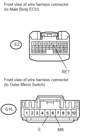
5.CHECK HARNESS AND CONNECTOR (OUTER MIRROR SWITCH - MAIN BODY ECU AND BODY GROUND)
a.
U164286E01
0.136,0.062 2.479,0.398 2.343,0.336 10 Front view of wire harness connector: (to Main Body ECU) 0.136,2.64 2.479,2.976 2.343,0.336 10 Front view of wire harness connector: (to Outer Mirror Switch) 0.501,1.428 0.747,1.584 0.246,0.156 10 E2 0.174,3.646 0.469,3.801 0.295,0.156 10 G16 2.125,2.361 2.500,2.531 0.375,0.170 10 RET 1.824,1.523 2.288,2.339 false 1.979,4.348 2.381,4.487 0.402,0.139 10 MR 1.315,4.329 1.499,4.467 0.184,0.139 10 E 1.876,3.938 2.065,4.307 false 1.661,3.933 1.442,4.294 false

Disconnect the E2 ECU connector.


b.

Disconnect the G16 switch connector.


c.

Measure the resistance according to the value(s) in the table below.

Standard Resistance:
Tester Connection Condition Specified Condition
E2-6 (RET) - G16-6 (MR) Always Below 1 Ω
G16-5 (E) - Body ground
G16-6 (MR) - Body ground Always 10 kΩ or higher


OK

REPLACE MAIN BODY ECU (COWL SIDE JUNCTION BLOCK LH)

NG

REPAIR OR REPLACE HARNESS OR CONNECTOR

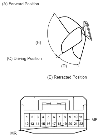
6.INSPECT OUTER MIRROR RETRACTOR LH
a.
B315169E01
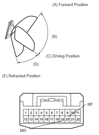
0.069,0.046 1.358,0.227 1.289,0.181 10 (A) Forward Position 0.228,1.869 1.462,2.063 1.235,0.194 10 (C) Driving Position 1.576,2.493 2.963,2.674 1.386,0.181 10 (E) Retracted Position 1.186,1.334 1.402,1.526 0.216,0.192 10 (B) 0.343,4.366 0.584,4.516 0.241,0.150 10 MR 3.053,3.918 3.300,4.068 0.247,0.150 10 MF 2.043,2.117 2.259,2.310 0.216,0.192 10 (D) 2.398,4.048 3.011,3.979 false 2.139,4.185 0.62,4.366 false

Remove the mirror LH (See page Vehicle Exterior>MIRROR (EXT)>OUTER REAR VIEW MIRROR>REMOVAL).


b.

For each mirror position: Disconnect the battery, set the mirror position by hand, connect the battery, and check the retractable mirror movement.

NOTICE:
·

Disconnect and reconnect the battery once between each mirror position check.

·

The mirror position cannot be changed manually when the battery is connected. To change the mirror position manually, the battery must be disconnected first.


OK:
Measurement Condition Mirror Position Specified Condition
Battery positive (+) → Terminal 19 (MR)
Battery negative (-) → Terminal 20 (MF)
Forward position (A) Moves from (A) to retracted position (E)
Battery negative (-) → Terminal 19 (MR)
Battery positive (+) → Terminal 20 (MF)
Forward position (A) Does not move
Battery positive (+) → Terminal 19 (MR)
Battery negative (-) → Terminal 20 (MF)
Position between forward position (A) and driving position (C) Moves from (B) to retracted position (E)
Battery negative (-) → Terminal 19 (MR)
Battery positive (+) → Terminal 20 (MF)
Position between forward position (A) and driving position (C) Moves from (B) to forward position (A)
Battery positive (+) → Terminal 19 (MR)
Battery negative (-) → Terminal 20 (MF)
Driving position (C) Moves from (C) to retracted position (E)
Battery negative (-) → Terminal 19 (MR)
Battery positive (+) → Terminal 20 (MF)
Driving position (C) Does not move
Battery positive (+) → Terminal 19 (MR)
Battery negative (-) → Terminal 20 (MF)
Position between driving position (C) and retracted position (E) Moves from (D) to retracted position (E)
Battery negative (-) → Terminal 19 (MR)
Battery positive (+) → Terminal 20 (MF)
Position between driving position (C) and retracted position (E) Moves from (D) to driving position (C)
Battery positive (+) → Terminal 19 (MR)
Battery negative (-) → Terminal 20 (MF)
Retracted position (E) Does not move
Battery negative (-) → Terminal 19 (MR)
Battery positive (+) → Terminal 20 (MF)
Retracted position (E) Moves from (E) to driving position (C)


OK

7.CHECK HARNESS AND CONNECTOR (OUTER REAR VIEW MIRROR LH - OUTER MIRROR CONTROL ECU)

NG

REPLACE OUTER MIRROR RETRACTOR LH

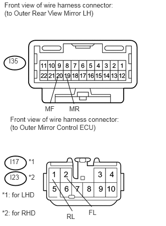
7.CHECK HARNESS AND CONNECTOR (OUTER REAR VIEW MIRROR LH - OUTER MIRROR CONTROL ECU)
a.
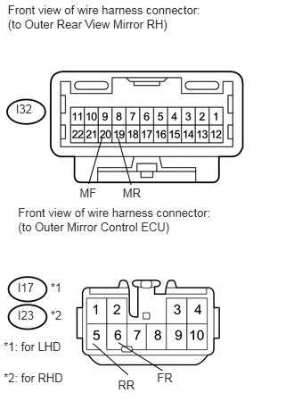
U164287E01
0.091,0.026 2.492,0.376 2.401,0.350 10 Front view of wire harness connector: (to Outer Rear View Mirror LH) 0.211,2.385 2.612,2.736 2.401,0.350 10 Front view of wire harness connector: (to Outer Mirror Control ECU) 1.379,4.398 1.619,4.548 0.241,0.150 10 RL 0.592,3.261 0.777,3.411 0.185,0.150 10 *1 0.043,3.952 0.753,4.102 0.710,0.150 10 *1: for LHD 0.043,4.32 0.795,4.538 0.752,0.218 10 *2: for RHD 0.207,3.261 0.433,3.411 0.226,0.150 10 I17 0.185,1.182 0.528,1.332 0.343,0.150 10 I35 1.836,4.312 2.095,4.462 0.258,0.150 10 FL 0.931,2.162 1.172,2.312 0.241,0.150 10 MF 1.435,2.162 1.682,2.312 0.247,0.150 10 MR 0.592,3.585 0.777,3.735 0.185,0.150 10 *2 0.207,3.586 0.433,3.736 0.226,0.150 10 I23 1.037,2.139 1.194,1.596 false 1.532,2.149 1.379,1.594 false 1.497,4.367 1.086,3.709 false 1.9,4.278 1.383,3.689 false

for LHD:

i.

Disconnect the I17 ECU connector.


ii.

Disconnect the I35 mirror connector.


iii.

Measure the resistance according to the value(s) in the table below.

Standard Resistance:
Tester Connection Condition Specified Condition
I17-1 (RL) - I35-19 (MR) Always Below 1 Ω
I17-2 (FL) - I35-20 (MF)
I35-19 (MR) - Body ground Always 10 kΩ or higher
I35-20 (MF) - Body ground


b.

for RHD:

i.

Disconnect the I23 ECU connector.


ii.

Disconnect the I35 mirror connector.


iii.

Measure the resistance according to the value(s) in the table below.

Standard Resistance:
Tester Connection Condition Specified Condition
I23-1 (RL) - I35-19 (MR) Always Below 1 Ω
I23-2 (FL) - I35-20 (MF)
I35-19 (MR) - Body ground Always 10 kΩ or higher
I35-20 (MF) - Body ground


OK

REPLACE OUTER MIRROR CONTROL ECU

NG

REPAIR OR REPLACE HARNESS OR CONNECTOR

8.INSPECT OUTER MIRROR RETRACTOR RH
a.
B315171E01
1.819,0.068 3.108,0.250 1.289,0.181 10 (A) Forward Position 1.597,1.855 2.832,2.049 1.235,0.194 10 (C) Driving Position 0.075,2.547 1.461,2.729 1.386,0.181 10 (E) Retracted Position 1.799,1.182 2.015,1.375 0.216,0.192 10 (B) 0.695,4.434 0.936,4.584 0.241,0.150 10 MR 3.037,3.533 3.284,3.683 0.247,0.150 10 MF 1.149,2.135 1.365,2.327 0.216,0.192 10 (D) 2.362,4.043 2.981,3.618 false 2.178,4.181 1.016,4.46 false

Remove the mirror RH (See page Vehicle Exterior>MIRROR (EXT)>OUTER REAR VIEW MIRROR>REMOVAL).


b.

For each mirror position: Disconnect the battery, set the mirror position by hand, connect the battery, and check the retractable mirror movement.

NOTICE:
·

Disconnect and reconnect the battery once between each mirror position check.

·

The mirror position cannot be changed manually when the battery is connected. To change the mirror position manually, the battery must be disconnected first.


OK:
Measurement Condition Mirror Position Specified Condition
Battery positive (+) → Terminal 19 (MR)
Battery negative (-) → Terminal 20 (MF)
Forward position (A) Moves from (A) to retracted position (E)
Battery negative (-) → Terminal 19 (MR)
Battery positive (+) → Terminal 20 (MF)
Forward position (A) Does not move
Battery positive (+) → Terminal 19 (MR)
Battery negative (-) → Terminal 20 (MF)
Position between forward position (A) and driving position (C) Moves from (B) to retracted position (E)
Battery negative (-) → Terminal 19 (MR)
Battery positive (+) → Terminal 20 (MF)
Position between forward position (A) and driving position (C) Moves from (B) to forward position (A)
Battery positive (+) → Terminal 19 (MR)
Battery negative (-) → Terminal 20 (MF)
Driving position (C) Moves from (C) to retracted position (E)
Battery negative (-) → Terminal 19 (MR)
Battery positive (+) → Terminal 20 (MF)
Driving position (C) Does not move
Battery positive (+) → Terminal 19 (MR)
Battery negative (-) → Terminal 20 (MF)
Position between driving position (C) and retracted position (E) Moves from (D) to retracted position (E)
Battery negative (-) → Terminal 19 (MR)
Battery positive (+) → Terminal 20 (MF)
Position between driving position (C) and retracted position (E) Moves from (D) to driving position (C)
Battery positive (+) → Terminal 19 (MR)
Battery negative (-) → Terminal 20 (MF)
Retracted position (E) Does not move
Battery negative (-) → Terminal 19 (MR)
Battery positive (+) → Terminal 20 (MF)
Retracted position (E) Moves from (E) to driving position (C)


OK

9.CHECK HARNESS AND CONNECTOR (OUTER REAR VIEW MIRROR RH - OUTER MIRROR CONTROL ECU)

NG

REPLACE OUTER MIRROR RETRACTOR RH

9.CHECK HARNESS AND CONNECTOR (OUTER REAR VIEW MIRROR RH - OUTER MIRROR CONTROL ECU)
a.
U164288E01
0.091,0.032 2.492,0.382 2.401,0.350 10 Front view of wire harness connector: (to Outer Rear View Mirror RH) 0.211,2.391 2.612,2.742 2.401,0.350 10 Front view of wire harness connector: (to Outer Mirror Control ECU) 1.379,4.404 1.619,4.554 0.241,0.150 10 RR 0.592,3.266 0.777,3.416 0.185,0.150 10 *1 0.043,3.958 0.753,4.108 0.710,0.150 10 *1: for LHD 0.043,4.325 0.795,4.475 0.752,0.150 10 *2: for RHD 0.207,3.267 0.433,3.417 0.226,0.150 10 I17 0.185,1.188 0.528,1.338 0.343,0.150 10 I32 1.836,4.318 2.095,4.468 0.258,0.150 10 FR 0.931,2.168 1.172,2.318 0.241,0.150 10 MF 1.435,2.168 1.682,2.318 0.247,0.150 10 MR 0.592,3.591 0.777,3.741 0.185,0.150 10 *2 0.207,3.592 0.433,3.742 0.226,0.150 10 I23 1.037,2.145 1.194,1.602 false 1.532,2.155 1.379,1.6 false 1.497,4.372 1.086,4.006 false 1.9,4.323 1.383,3.995 false

for LHD:

i.

Disconnect the I17 ECU connector.


ii.

Disconnect the I32 mirror connector.


iii.

Measure the resistance according to the value(s) in the table below.

Standard Resistance:
Tester Connection Condition Specified Condition
I17-5 (RR) - I32-19 (MR) Always Below 1 Ω
I17-6 (FR) - I32-20 (MF)
I32-19 (MR) - Body ground Always 10 kΩ or higher
I32-20 (MF) - Body ground


b.

for RHD:

i.

Disconnect the I23 ECU connector.


ii.

Disconnect the I32 mirror connector.


iii.

Measure the resistance according to the value(s) in the table below.

Standard Resistance:
Tester Connection Condition Specified Condition
I23-5 (RR) - I32-19 (MR) Always Below 1 Ω
I23-6 (FR) - I32-20 (MF)
I32-19 (MR) - Body ground Always 10 kΩ or higher
I32-20 (MF) - Body ground


OK

REPLACE OUTER MIRROR CONTROL ECU

NG

REPAIR OR REPLACE HARNESS OR CONNECTOR