RM2660E
_59
Vehicle Exterior
_052854
WIPER / WASHER
_0255769
WIPER AND WASHER SYSTEM(w/ Rain Sensor)
J
WIPER / WASHER WIPER AND WASHER SYSTEM(w/ Rain Sensor) Headlight Signal Circuit
DESCRIPTION
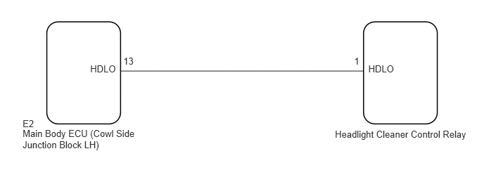
The headlight cleaner control relay detects the low beam headlights status.
WIRING DIAGRAM
1.336,0.935 1.779,1.096
0.443,0.160
10
HDLO
1.826,0.823 2.029,0.984
0.204,0.160
10
13
5.454,0.935 5.898,1.096
0.443,0.160
10
HDLO
5.244,0.823 5.354,0.984
0.110,0.160
10
1
0.335,1.746 0.547,1.921
0.212,0.175
10
E2
0.335,1.894 2.324,2.237
1.989,0.343
10
Main Body ECU (Cowl Side Junction Block LH)
4.96,1.902 6.994,2.092
2.034,0.190
10
Headlight Cleaner Control Relay
PROCEDURE
1.CHECK LOW BEAM HEADLIGHTS OPERATION
a.
Check that the low beam headlights operate normally (See page Vehicle Exterior>LIGHTING (EXT)>LIGHTING SYSTEM>OPERATION CHECK).
- OK:
Low beam headlights operate normally.
OK
2.CHECK HARNESS AND CONNECTOR (HEADLIGHT CLEANER CONTROL RELAY - MAIN BODY ECU)
NG
GO TO LIGHTING SYSTEM
2.CHECK HARNESS AND CONNECTOR (HEADLIGHT CLEANER CONTROL RELAY - MAIN BODY ECU)
a.
0.171,0.041 2.496,0.565
2.325,0.524
10
Front view of wire harness connector: (to Main Body ECU [Cowl Side Junction Block LH])
0.188,2.43 2.513,2.778
2.325,0.348
10
Front view of wire harness connector: (to Headlight Cleaner Control Relay)
0.198,2.042 0.637,2.200
0.439,0.158
10
HDLO
1.371,1.911 0.724,2.116
false
0.309,3.873 0.748,4.031
0.439,0.158
10
HDLO
1.483,3.742 0.835,3.947
false
0.431,1.334 0.630,1.512
0.200,0.179
10
E2
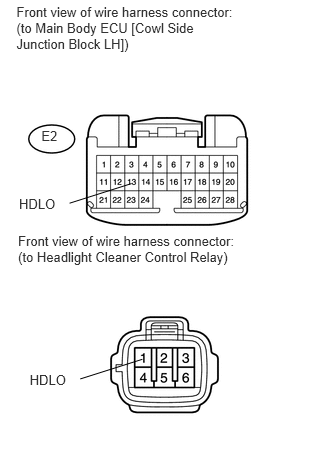
Disconnect the E2 main body ECU (cowl side junction block LH) connector.
b.
Disconnect the headlight cleaner control relay connector.
c.
Measure the resistance according to the value(s) in the table below.
- Standard Resistance:
Tester Connection Condition Specified Condition 1 (HDLO) - E2-13 (HDLO) Always Below 1 Ω 1 (HDLO) - Body ground Always 10 kΩ or higher
OK
3.CHECK MAIN BODY ECU (COWL SIDE JUNCTION BLOCK LH)
NG
REPAIR OR REPLACE HARNESS OR CONNECTOR
3.CHECK MAIN BODY ECU (COWL SIDE JUNCTION BLOCK LH)
a.
0.979,1.719 1.448,1.313
true
0.76,1.719 1.021,1.885
0.26,0.167
10
false
HDLO
0.292,0.094 2.708,0.615
2.417,0.521
10
false
Front view of wire harness connector: (to Headlight Cleaner Control Relay)
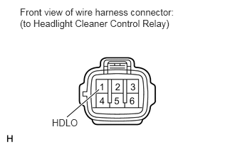
Disconnect the headlight cleaner control relay connector.
b.
Measure the voltage according to the value(s) in the table below.
- Standard Voltage:
Tester Connection Switch Condition Specified Condition 1 (HDLO) - Body ground Engine switch on (IG)
Headlight dimmer switch in HEAD11 to 14 V 1 (HDLO) - Body ground Engine switch on (IG)
Headlight dimmer switch not in HEADBelow 1 V
OK
PROCEED TO NEXT SUSPECTED AREA SHOWN IN PROBLEM SYMPTOMS TABLE
(See pageVehicle Exterior>WIPER / WASHER>WIPER AND WASHER SYSTEM(w/ Rain Sensor)>PROBLEM SYMPTOMS TABLE)
NG
REPLACE MAIN BODY ECU (COWL SIDE JUNCTION BLOCK LH)