LIGHTING (EXT) RELAY ON-VEHICLE INSPECTION
PROCEDURE

 1.INSPECT HEADLIGHT RELAY (H-LP LO, H-LP LH Relay)
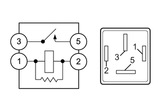
Measure the resistance according to the value(s) in the table below.
- Standard Resistance:
Tester Connection Condition Specified Condition 3 - 5 Battery voltage is not applied to terminals 1 and 2 10 kΩ or higher Battery voltage is applied to terminals 1 and 2 Below 1 Ω
If the result is not as specified, replace the headlight relay.
2.INSPECT HEADLIGHT RELAY (H-LP HI, H-LP RH Relay)
Measure the resistance according to the value(s) in the table below.
- Standard Resistance:
Tester Connection Condition Specified Condition 3 - 5 Battery voltage is not applied to terminals 1 and 2 10 kΩ or higher Battery voltage is applied to terminals 1 and 2 Below 1 Ω
If the result is not as specified, replace the headlight relay.
3.INSPECT FOG LIGHT RELAY (FR FOG)
Measure the resistance according to the value(s) in the table below.
- Standard Resistance:
Tester Connection Condition Specified Condition 3 - 5 Battery voltage is not applied to terminals 1 and 2 10 kΩ or higher Battery voltage is applied to terminals 1 and 2 Below 1 Ω
If the result is not as specified, replace the fog relay.
895A0
4.INSPECT STOP LIGHT CONTROL RELAY ASSEMBLY
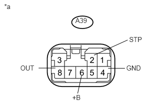
Measure the voltage according to the value(s) in the table below.
- Standard Voltage:
Tester Connection Switch Condition Specified Condition A39-6 (+B) - A39-4 (GND) Always 11 to 14 V A39-2 (STP) - Body grand Brake pedal depressed 11 to 14 V Brake pedal not depressed Below 1 V A39-8 (OUT) - Body grand Brake pedal depressed 11 to 14 V Brake pedal not depressed Below 1 V
If the result is not as specified, replace the stop light control relay assembly.
| *a | Component with harness connected
(Stop Light Control Relay Assembly |
5.INSPECT INTEGRATION RELAY (DRL)
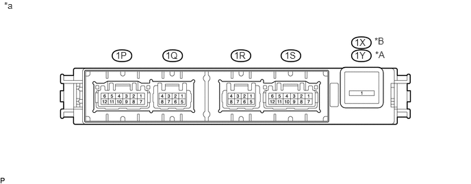
| *A | for LHD | *B | for RHD |
| *a | Component without harness connected
(Integration Relay) |
- | - |
- NOTICE:
- ·
The DRL relay is built into the integration relay.
·Before performing the relay inspections for the relays of the integration relay, inspect the DRL fuse.
Inspect the DRL relay.
Measure the resistance and voltage according to the value(s) in the table below.
- for LHD:
Standard Resistance: Tester Connection Condition Specified Condition 1Y-1 - 1R-3 Always 10 kΩ or higher
Standard Voltage: Tester Connection Condition Specified Condition 1R-3 - Body ground Battery voltage is applied to terminals 1Y-1 and 1R-4 11 to 14 V
- for RHD:
Standard Resistance: Tester Connection Condition Specified Condition 1X-1 - 1R-3 Always 10 kΩ or higher
Standard Voltage: Tester Connection Condition Specified Condition 1R-3 - Body ground Battery voltage is applied to terminals 1X-1 and 1R-4 11 to 14 V
If the result is not as specified, replace the integration relay.