RM2660E
_59
Vehicle Exterior
_052855
LIGHTING (EXT)
_0255806
STOP LIGHT SWITCH
A
LIGHTING (EXT) STOP LIGHT SWITCH INSTALLATION
PROCEDURE

 84345
1.INSTALL STOP LIGHT SWITCH MOUNTING ADJUSTER
a.
Install a stop light switch mounting adjuster to the pedal support.
2.INSTALL STOP LIGHT SWITCH
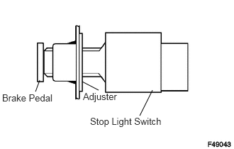
a.
2.24,1.323 2.052,1.698
false
1.208,1.198 1.448,1.323
false
0.583,1.177 0.521,1.344
false
1.219,1.333 1.771,1.531
0.552,0.198
10
false
Adjuster
0.031,1.354 0.823,1.531
0.792,0.177
10
false
Brake Pedal
1.323,1.698 2.438,1.885
1.115,0.188
10
false
Stop Light Switch
Insert the stop light switch to the adjuster until it just touches the brake pedal.
- NOTICE:
-
Do not depress the brake pedal.
b.
1.851,1.226 1.936,1.346
false
0.573,0.688 0.521,0.206
false
0.077,0.071 1.039,0.373
0.961,0.302
10
Shaft
1.282,1.342 2.389,1.552
1.107,0.210
10
Stop Light Switch
0.097,1.702 2.185,1.978
2.088,0.276
10
1.5 to 2.5 mm
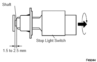
Turn the stop light switch quarter in clockwise to install it.
- NOTICE:
- ·
Do not depress the brake pedal.
·Do not apply thrust force 98 N (9.99 kgf) or more to the switch body.
·Do not apply silicone grease on the switch body.
- Torque:
- 1.5 N*m (15 kgf*cm, 13 in.*lbf)
c.
Check the stop light switch clearance.
- Stop light switch clearance:
1.5 to 2.5 mm (0.0590 to 0.0984 in.)
d.
Connect the wire harness clamp to the pedal support.
e.
Connect the connector to the stop light switch.