Home › Vehicle Exterior › LIGHTING (EXT) › LIGHTING SYSTEM › 2014.08–2015.08
RM2660E _59 Vehicle Exterior _052855 LIGHTING (EXT) _0255811 LIGHTING SYSTEM J

LIGHTING (EXT)  LIGHTING SYSTEM  Door Courtesy Light Circuit  


DESCRIPTION

The door courtesy light turns on when the door is opened and turns off when closed.

WIRING DIAGRAM
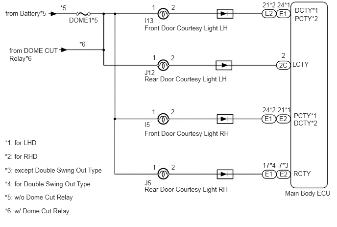
E274436E02
3.073,0.354 3.302,0.542 0.229,0.188 10 false I13 3.073,0.51 5.438,0.677 2.365,0.167 10 false Front Door Courtesy Light LH 3.073,1.458 3.365,1.646 0.292,0.188 10 false J12 3.073,1.594 5.438,1.76 2.365,0.167 10 false Rear Door Courtesy Light LH 3.073,2.75 5.042,3 1.969,0.25 10 false Front Door Courtesy Light RH 3.073,2.563 3.344,2.76 0.271,0.198 10 false I5 3.073,3.802 3.385,4.042 0.313,0.24 10 false J5 3.073,3.938 5.115,4.135 2.042,0.198 10 false Rear Door Courtesy Light RH 3.229,0.073 3.385,0.26 0.156,0.188 10 false 1 3.646,0.073 3.781,0.271 0.135,0.198 10 false 2 3.24,1.135 3.344,1.292 0.104,0.156 10 false 1 3.635,1.146 3.74,1.302 0.104,0.156 10 false 2 3.229,2.292 3.438,2.5 0.208,0.208 10 false 1 3.635,2.292 3.813,2.5 0.177,0.208 10 false 2 3.24,3.469 3.448,3.656 0.208,0.188 10 false 1 3.646,3.469 3.813,3.656 0.167,0.188 10 false 2 5.635,0.198 5.896,0.438 0.26,0.24 10 false E2 5.938,0.208 6.208,0.417 0.271,0.208 10 false E1 5.625,2.438 5.854,2.615 0.229,0.177 10 false E1 5.938,2.438 6.167,2.615 0.229,0.177 10 false E2 5.938,1.302 6.188,1.51 0.25,0.208 10 false 2C 5.583,0.021 5.927,0.188 0.344,0.167 10 false 21*2 5.896,0.021 6.24,0.188 0.344,0.167 10 false 24*1 5.583,2.25 5.927,2.417 0.344,0.167 10 false 24*2 5.906,2.25 6.25,2.417 0.344,0.167 10 false 21*1 5.99,1.094 6.167,1.281 0.177,0.188 10 false 2 5.635,3.615 5.865,3.792 0.229,0.177 10 false E1 5.948,3.615 6.177,3.792 0.229,0.177 10 false E2 5.583,3.427 5.906,3.594 0.323,0.167 10 false 17*4 5.927,3.427 6.177,3.594 0.25,0.167 10 false 7*3 6.271,0.135 6.917,0.302 0.646,0.167 10 false DCTY*1 6.271,0.313 6.917,0.479 0.646,0.167 10 false PCTY*2 6.25,2.375 6.844,2.594 0.594,0.219 10 false PCTY*1 6.25,2.531 6.802,2.792 0.552,0.26 10 false DCTY*2 6.219,1.281 6.677,1.51 0.458,0.229 10 false LCTY 6.24,3.604 6.708,3.865 0.469,0.26 10 false RCTY 0.115,0.198 1.219,0.365 1.104,0.167 10 false from Battery*5 1.469,0.344 2.167,0.51 0.698,0.167 10 false DOME1*5 0.104,2.948 0.979,3.125 0.875,0.177 10 false *1: for LHD 6.063,4.021 7.083,4.271 1.021,0.25 10 false Main Body ECU 0.104,4.396 1.854,4.615 1.75,0.219 10 false *6: w/ Dome Cut Relay 0.104,4.104 1.854,4.323 1.75,0.219 10 false *5: w/o Dome Cut Relay 0.104,3.823 2.115,4.042 2.01,0.219 10 false *4: for Double Swing Out Type 0.104,3.531 2.313,3.75 2.208,0.219 10 false *3: except Double Swing Out Type 0.104,3.24 0.979,3.417 0.875,0.177 10 false *2: for RHD 0.198,0.99 1.313,1.396 1.115,0.406 10 false from DOME CUT Relay*6 1.688,0.854 1.906,1.021 0.219,0.167 10 false *6 1.281,0.083 1.5,0.25 0.219,0.167 10 false *5

PROCEDURE

1.CHECK OPERATION OF DOOR COURTESY LIGHT
a.

When a door is opened, check that the following lights do not illuminate.


Result
Result Proceed to
All door courtesy light does not illuminate A
Front door courtesy light LH does not illuminate B
Front door courtesy light RH does not illuminate C
Rear door courtesy light LH does not illuminate D
Rear door courtesy light RH does not illuminate E


A

2.INSPECT FUSE (DOME1)

B

4.INSPECT DOOR COURTESY LIGHT (FRONT DOOR LH)

C

6.INSPECT DOOR COURTESY LIGHT (FRONT DOOR RH)

D

8.INSPECT COURTESY LIGHT (REAR DOOR LH)

E

10.INSPECT DOOR COURTESY LIGHT (REAR DOOR RH)
2.INSPECT FUSE (DOME1)
a.

Remove the DOME1 fuse from the engine room junction block.


b.

Measure the resistance according to the value(s) in the table below.

Standard Resistance:
Tester Connection Condition Specified Condition
DOME1 fuse Always Below 1 Ω


OK

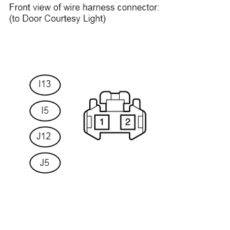
3.CHECK HARNESS AND CONNECTOR (DOOR COURTESY LIGHT - BODY GROUND)

NG

REPLACE FUSE

3.CHECK HARNESS AND CONNECTOR (DOOR COURTESY LIGHT - BODY GROUND)
a.
U156627E03
0.135,0.021 2.49,0.354 2.354,0.333 10 false Front view of wire harness connector: (to Door Courtesy Light) 0.573,1.167 0.865,1.365 0.292,0.198 10 false I13 0.615,1.563 0.823,1.781 0.208,0.219 10 false I5 0.542,1.948 0.844,2.156 0.302,0.208 10 false J12 0.594,2.344 0.833,2.542 0.24,0.198 10 false J5

Disconnect the I13, I5, J12 and J5 ECU connectors.


b.

Measure the voltage according to the value(s) in the table below.

Standard Voltage:
Tester Connection Switch Condition Specified Condition
I13-1 - Body ground Always 11 to 14 V
J12-1 - Body ground
I5-1 - Body ground
J5-1 - Body ground


OK

PROCEED TO NEXT INSPECTION PROCEDURE SHOWN IN PROBLEM SYMPTOMS TABLE

NG

REPAIR OR REPLACE HARNESS OR CONNECTOR

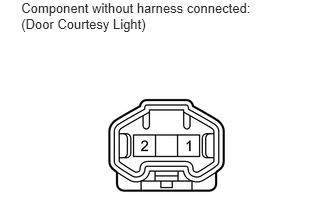
4.INSPECT DOOR COURTESY LIGHT (FRONT DOOR LH)
a.
E147248E05
0.221,0 2.736,0.371 2.515,0.371 10 Component without harness connected: (Door Courtesy Light)

Remove the door courtesy light connector.


b.

Check that the door courtesy light comes on.

OK:
Measurement Condition Specified Condition
Battery positive (+) - Terminal 2
Battery positive (-) - Terminal 1
Light illumination


OK

END

NG

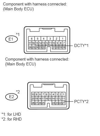
5.CHECK HARNESS AND CONNECTOR (MAIN BODY ECU - BODY GROUND)
a.
U166073E02
1.24,1.573 2.5,1.573 false 2.188,3.49 2.521,3.49 false 0.104,0.052 2.427,0.375 2.323,0.323 10 false Component with harness connected: (Main Body ECU) 0.177,1.948 2.5,2.271 2.323,0.323 10 false Component with harness connected: (Main Body ECU) 0.292,1.26 0.51,1.417 0.219,0.156 10 false E1 0.313,3.24 0.531,3.396 0.219,0.156 10 false E2 0.052,3.844 0.813,4.344 0.76,0.5 10 false *1: for LHD *2: for RHD 2.552,1.479 3.094,1.667 0.542,0.188 10 false DCTY*1 2.552,3.406 3.094,3.604 0.542,0.198 10 false PCTY*2 0.552,3.073 0.74,3.25 0.188,0.177 10 false *2 0.552,1.104 0.74,1.281 0.188,0.177 10 false *1

Remove the main body ECU.


b.

for LHD:

i.

Measure the voltage according to the value(s) in the table below.

Standard Voltage:
Tester Connection Condition Specified Condition
E1-24 (DCTY) - Body ground Always 11 to 14V


c.

for RHD:

i.

Measure the voltage according to the value(s) in the table below.

Standard Voltage:
Tester Connection Condition Specified Condition
E2-21 (PCTY) - Body ground Always 11 to 14V


OK

REPLACE MAIN BODY ECU

NG

REPAIR OR REPLACE HARNESS OR CONNECTOR

6.INSPECT DOOR COURTESY LIGHT (FRONT DOOR RH)
a.
E147248E05
0.221,0 2.736,0.371 2.515,0.371 10 Component without harness connected: (Door Courtesy Light)

Remove the door courtesy light connector.


b.

Check that the door courtesy light comes on.

OK:
Measurement Condition Specified Condition
Battery positive (+) - Terminal 2
Battery positive (-) - Terminal 1
Light illumination


OK

END

NG

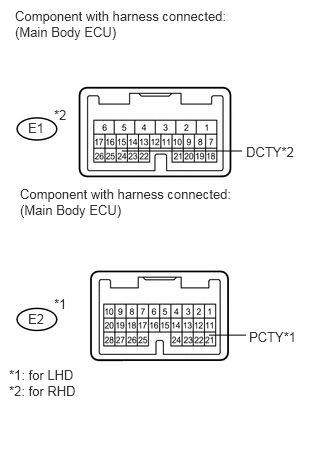
7.CHECK HARNESS AND CONNECTOR (MAIN BODY ECU - BODY GROUND)
a.
U166074E02
1.271,1.573 2.521,1.573 false 2.177,3.49 2.563,3.49 false 0.156,0.083 2.479,0.479 2.323,0.396 10 false Component with harness connected: (Main Body ECU) 0.208,1.938 2.531,2.313 2.323,0.375 10 false Component with harness connected: (Main Body ECU) 0.292,1.25 0.521,1.427 0.229,0.177 10 false E1 0.292,3.24 0.531,3.417 0.24,0.177 10 false E2 0.094,3.823 0.854,4.323 0.76,0.5 10 false *1: for LHD *2: for RHD 2.563,1.5 3.104,1.646 0.542,0.146 10 false DCTY*2 2.594,3.427 3.135,3.573 0.542,0.146 10 false PCTY*1 0.563,3.083 0.781,3.229 0.219,0.146 10 false *1 0.563,1.115 0.781,1.26 0.219,0.146 10 false *2

Remove the main body ECU.


b.

for LHD:

i.

Measure the voltage according to the value(s) in the table below.

Standard Voltage:
Tester Connection Condition Specified Condition
E2-21 (PCTY) - Body ground Always 11 to 14V


c.

for RHD:

i.

Measure the voltage according to the value(s) in the table below.

Standard Voltage:
Tester Connection Condition Specified Condition
E1-24 (DCTY) - Body ground Always 11 to 14V


OK

REPLACE MAIN BODY ECU

NG

REPAIR OR REPLACE HARNESS OR CONNECTOR

8.INSPECT COURTESY LIGHT (REAR DOOR LH)
a.
E147248E05
0.221,0 2.736,0.371 2.515,0.371 10 Component without harness connected: (Door Courtesy Light)

Remove the door courtesy light connector.


b.

Check that the door courtesy light comes on.

OK:
Measurement Condition Specified Condition
Battery positive (+) - Terminal 2
Battery positive (-) - Terminal 1
Light illumination


OK

END

NG

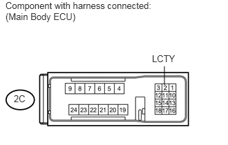
9.CHECK HARNESS AND CONNECTOR (MAIN BODY ECU - BODY GROUND)
a.
U165959E02
2.479,1.281 2.479,1 false 0.083,0 2.51,0.344 2.427,0.344 10 false Component with harness connected: (Main Body ECU) 0.208,1.406 0.438,1.594 0.229,0.188 10 false 2C 2.292,0.802 2.74,1.031 0.448,0.229 10 false LCTY

Remove the main body ECU.


b.

Measure the voltage according to the value(s) in the table below.

Standard Voltage:
Tester Connection Condition Specified Condition
2C-2 (LCTY) - Body ground Always 11 to 14V


OK

REPLACE MAIN BODY ECU

NG

REPAIR OR REPLACE HARNESS OR CONNECTOR

10.INSPECT DOOR COURTESY LIGHT (REAR DOOR RH)
a.
E147248E05
0.221,0 2.736,0.371 2.515,0.371 10 Component without harness connected: (Door Courtesy Light)

Remove the door courtesy light connector.


b.

Check that the door courtesy light comes on.

OK:
Measurement Condition Specified Condition
Battery positive (+) - Terminal 2
Battery positive (-) - Terminal 1
Light illumination


OK

END

NG

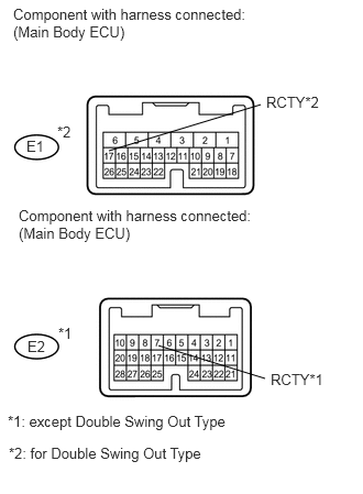
11.CHECK HARNESS AND CONNECTOR (MAIN BODY ECU - BODY GROUND)
a.
U166075E02
1.031,1.427 2.469,0.99 false 1.5,3.271 2.51,3.583 false 0.125,0.052 2.448,0.375 2.323,0.323 10 false Component with harness connected: (Main Body ECU) 0.177,1.958 2.563,2.281 2.385,0.323 10 false Component with harness connected: (Main Body ECU) 0.25,1.302 0.5,1.469 0.25,0.167 10 false E1 0.26,3.198 0.563,3.406 0.302,0.208 10 false E2 2.521,0.885 3.083,1.052 0.563,0.167 10 false RCTY*2 2.563,3.51 3.104,3.698 0.542,0.188 10 false RCTY*1 0.083,4.208 2.031,4.417 1.948,0.208 10 false *2: for Double Swing Out Type 0.073,3.906 2.302,4.115 2.229,0.208 10 false *1: except Double Swing Out Type 0.552,3.073 0.76,3.219 0.208,0.146 10 false *1 0.542,1.167 0.771,1.344 0.229,0.177 10 false *2

Remove the main body ECU.


b.

except Double Swing Out Type:

i.

Measure the voltage according to the value(s) in the table below.

Standard Voltage:
Tester Connection Condition Specified Condition
E2-7 (RCTY) - Body ground Always 11 to 14V


c.

for Double Swing Out Type:

i.

Measure the voltage according to the value(s) in the table below.

Standard Voltage:
Tester Connection Condition Specified Condition
E1-17 (RCTY) - Body ground Always 11 to 14V


OK

REPLACE MAIN BODY ECU

NG

REPAIR OR REPLACE HARNESS OR CONNECTOR