LIGHTING (EXT) LIGHTING SYSTEM Door Courtesy Light Circuit
DESCRIPTION
The door courtesy light turns on when the door is opened and turns off when closed.
WIRING DIAGRAM
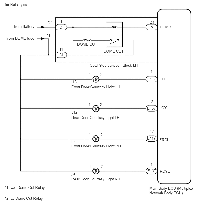
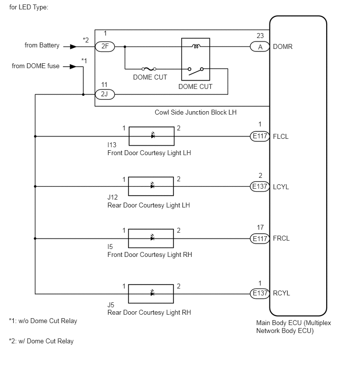
CAUTION / NOTICE / HINT
- NOTICE:
- ·
Inspect the fuses for circuits related to this system before performing the following inspection procedure.
·If the main body ECU (multiplex network body ECU) is replaced, refer to the Service Bulletin.
PROCEDURE
When a door is opened, check that the following lights do not illuminate.
| Result | Proceed to |
|---|---|
| All door courtesy light does not illuminate | A |
| Front door courtesy light LH does not illuminate | B |
| Front door courtesy light RH does not illuminate | C |
| Rear door courtesy light LH does not illuminate | D |
| Rear door courtesy light RH does not illuminate | E |
A
B
C
D
E
Remove the cowl side junction block LH.
Measure the resistance according to the value(s) in the table below.
- Standard Resistance:
Tester Connection Condition Specified Condition 2F-1 - 2J-11 Battery voltage not applied to terminals 2F-1 and A-23 10 kΩ or higher Battery voltage applied to terminals 2F-1 and A-23 Below 1 Ω
OK
NG
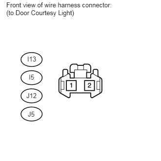
Disconnect the I13, I5, J12 and J5 ECU connectors.
Measure the voltage according to the value(s) in the table below.
- Standard Voltage:
Tester Connection Switch Condition Specified Condition I13-1 - Body ground Always 11 to 14 V J12-1 - Body ground I5-1 - Body ground J5-1 - Body ground
OK
NG
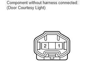
Remove the door courtesy light connector.
Check that the door courtesy light comes on.
- OK:
Measurement Condition Specified Condition Battery positive (+) - Terminal 2
Battery positive (-) - Terminal 1Light illumination
OK
NG
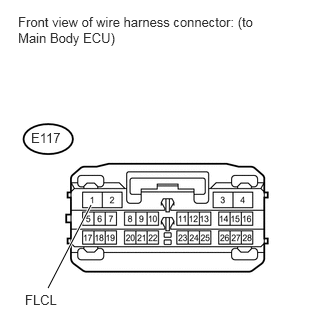
Disconnect the E117 main body ECU connectors.
Measure the voltage according to the value(s) in the table below.
- Standard Voltage:
Tester Connection Condition Specified Condition E117-1 (FLCL) - Body ground Ignition switch ON 11 to 14 V
OK
NG
Remove the door courtesy light connector.
Check that the door courtesy light comes on.
- OK:
Measurement Condition Specified Condition Battery positive (+) - Terminal 2
Battery positive (-) - Terminal 1Light illumination
OK
NG
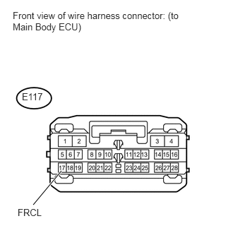
Disconnect the E117 main body ECU connectors.
Measure the voltage according to the value(s) in the table below.
- Standard Voltage:
Tester Connection Condition Specified Condition E117-17 (FRCL) - Body ground Ignition switch ON 11 to 14 V
OK
NG
Remove the door courtesy light connector.
Check that the door courtesy light comes on.
- OK:
Measurement Condition Specified Condition Battery positive (+) - Terminal 2
Battery positive (-) - Terminal 1Light illumination
OK
NG
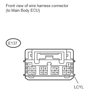
Disconnect the E137 main body ECU connectors.
Measure the voltage according to the value(s) in the table below.
- Standard Voltage:
Tester Connection Condition Specified Condition E137-2 (LCYL) - Body ground Ignition switch ON 11 to 14 V
OK
NG
Remove the door courtesy light connector.
Check that the door courtesy light comes on.
- OK:
Measurement Condition Specified Condition Battery positive (+) - Terminal 2
Battery positive (-) - Terminal 1Light illumination
OK
NG
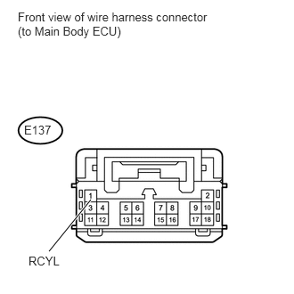
Disconnect the E137 main body ECU connectors.
Measure the voltage according to the value(s) in the table below.
- Standard Voltage:
Tester Connection Condition Specified Condition E137-1 (RCYL) - Body ground Ignition switch ON 11 to 14 V
OK
NG