Home › Vehicle Exterior › LIGHTING (EXT) › LIGHTING SYSTEM › from 2015.08
RM2660E _59 Vehicle Exterior _052855 LIGHTING (EXT) _0255811 LIGHTING SYSTEM J

LIGHTING (EXT)  LIGHTING SYSTEM  Door Illumination Circuit  


DESCRIPTION

The rear door illumination is controlled by the main body ECU.

WIRING DIAGRAM
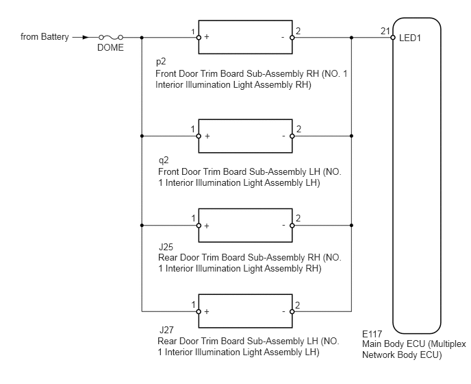
E326533E05
0.313,0.469 1.083,0.667 0.771,0.198 10 false from Battery 1.479,0.635 2.094,0.833 0.615,0.198 10 false DOME 6.073,0.49 6.688,0.688 0.615,0.198 10 false LED1 5.51,5.135 7.156,5.563 1.646,0.427 10 false Main Body ECU (Multiplex Network Body ECU) 5.51,4.99 6.125,5.188 0.615,0.198 10 false E117 2.365,1.031 5.292,1.427 2.927,0.396 10 false Front Door Trim Board Sub-Assembly RH (NO. 1 Interior Illumination Light Assembly RH) 2.406,2.521 5.198,3.104 2.792,0.583 10 false Front Door Trim Board Sub-Assembly LH (NO. 1 Interior Illumination Light Assembly LH) 2.375,0.844 2.833,1.042 0.458,0.198 10 false p2 5.792,0.385 6.104,0.583 0.313,0.198 10 false 21 2.417,2.344 2.875,2.542 0.458,0.198 10 false q2 3.104,3.344 3.26,3.542 0.156,0.198 10 false + 3.104,0.469 3.26,0.667 0.156,0.198 10 false + 4.281,0.479 4.438,0.677 0.156,0.198 9 false - 4.292,3.323 4.448,3.521 0.156,0.198 10 false - 2.906,0.406 3.063,0.604 0.156,0.198 8 false 1 2.896,1.875 3.052,2.073 0.156,0.198 10 false 1 4.51,1.875 4.667,2.073 0.156,0.198 10 false 2 4.5,0.385 4.656,0.583 0.156,0.198 10 false 2 2.417,3.667 2.875,3.865 0.458,0.198 10 false J25 2.427,4.927 2.885,5.125 0.458,0.198 10 false J27 2.406,3.823 5.219,4.344 2.813,0.521 10 false Rear Door Trim Board Sub-Assembly RH (NO. 1 Interior Illumination Light Assembly RH) 2.396,5.094 5.25,5.5 2.854,0.406 10 false Rear Door Trim Board Sub-Assembly LH (NO. 1 Interior Illumination Light Assembly LH) 2.906,3.229 3.063,3.427 0.156,0.198 10 false 1 2.906,4.542 3.063,4.74 0.156,0.198 10 false 1 4.5,3.229 4.656,3.427 0.156,0.198 10 false 2 4.49,4.552 4.646,4.75 0.156,0.198 10 false 2 3.104,4.646 3.26,4.844 0.156,0.198 10 false + 4.292,4.635 4.448,4.833 0.156,0.198 10 false - 3.115,1.979 3.271,2.177 0.156,0.198 10 false + 4.292,1.969 4.448,2.167 0.156,0.198 10 false -

CAUTION / NOTICE / HINT

NOTICE:
·

Inspect the fuses for circuits related to this system before performing the following inspection procedure.

·

If the main body ECU (multiplex network body ECU) is replaced, refer to the Service Bulletin.


PROCEDURE

1.PERFORM ACTIVE TEST USING GTS (INTERIOR ILLUMINATION LIGHT1)
a.

Operate the GTS according to the steps on the display and select "Active Test".

Main Body
Tester Display Test Part Control Range Diagnostic Note
Interior Illumination Light1 door illumination light* OFF or ON -

*: 15 seconds after turning the engine switch off, check the operation once the rear door illumination turns off.


OK:

Rear door illumination illuminates.


Result
Result Proceed
OK A
NG (Front Door LH Side) B
NG (Front Door RH Side) C
NG (Rear Door LH Side) D
NG (Rear Door RH Side) E


A

PROCEED TO NEXT SUSPECTED AREA SHOWN IN PROBLEM SYMPTOMS TABLE

B

2.CHECK HARNESS AND CONNECTOR (MAIN BODY ECU - FRONT DOOR TRIM BOARD SUB-ASSEMBLY LH)

C

4.CHECK HARNESS AND CONNECTOR (MAIN BODY ECU - FRONT DOOR TRIM BOARD SUB-ASSEMBLY RH)

D

6.CHECK HARNESS AND CONNECTOR (MAIN BODY ECU - REAR DOOR TRIM BOARD SUB-ASSEMBLY LH)

E

8.CHECK HARNESS AND CONNECTOR (MAIN BODY ECU - REAR DOOR TRIM BOARD SUB-ASSEMBLY RH)
2.CHECK HARNESS AND CONNECTOR (MAIN BODY ECU - FRONT DOOR TRIM BOARD SUB-ASSEMBLY LH)
a.

Remove the front door trim board sub-assembly LH.


b.

Remove the DOME fuse from cowl side junction block LH.


c.

Remove the main body ECU (multiplex network body ECU) from the junction block assembly LH.


d.

Measure the resistance according to the value(s) in the table below.

Standard Resistance:
Tester Connection Condition Specified Condition
E117-21 (LED1) - q2-2 (-) Always Below 1 Ω
2 (DOME fuse holder) - q2-1 (+) Always Below 1 Ω
E117-21 (LED1) - Body ground Always 10 kΩ or higher
2 (DOME fuse holder) or q2-1 (+) - Body ground Always 10 kΩ or higher


OK

3.INSPECT FRONT DOOR TRIM BOARD SUB-ASSEMBLY LH

NG

REPAIR OR REPLACE HARNESS OR CONNECTOR

3.INSPECT FRONT DOOR TRIM BOARD SUB-ASSEMBLY LH
a.

Temporarily replace the eront door trim board sub-assembly LH with a new or normally functioning one.

OK:

The illumination illuminates normally.


OK

END (FRONT DOOR TRIM BOARD SUB-ASSEMBLY LH IS DEFECTIVE)

NG

REPLACE MAIN BODY ECU (MULTIPLEX NETWORK BODY ECU)

4.CHECK HARNESS AND CONNECTOR (MAIN BODY ECU - FRONT DOOR TRIM BOARD SUB-ASSEMBLY RH)
a.

Remove the front door trim board sub-assembly RH.


b.

Remove the DOME fuse from cowl side junction block LH.


c.

Remove the main body ECU (multiplex network body ECU) from the junction block assembly LH.


d.

Measure the resistance according to the value(s) in the table below.

Standard Resistance:
Tester Connection Condition Specified Condition
E117-21 (LED1) - p2-2 (-) Always Below 1 Ω
2 (DOME fuse holder) - p2-1 (+) Always Below 1 Ω
E117-21 (LED1) - Body ground Always 10 kΩ or higher
2 (DOME fuse holder) or p2-1 (+) - Body ground Always 10 kΩ or higher


OK

5.INSPECT FRONT DOOR TRIM BOARD SUB-ASSEMBLY RH

NG

REPAIR OR REPLACE HARNESS OR CONNECTOR

5.INSPECT FRONT DOOR TRIM BOARD SUB-ASSEMBLY RH
a.

Temporarily replace the front door trim board sub-assembly RH with a new or normally functioning one.

OK:

The illumination illuminates normally.


OK

END (FRONT DOOR TRIM BOARD SUB-ASSEMBLY RH IS DEFECTIVE)

NG

REPLACE MAIN BODY ECU (MULTIPLEX NETWORK BODY ECU)

6.CHECK HARNESS AND CONNECTOR (MAIN BODY ECU - REAR DOOR TRIM BOARD SUB-ASSEMBLY LH)
a.

Remove the rear door trim board sub-assembly LH.


b.

Remove the DOME fuse from cowl side junction block LH.


c.

Remove the main body ECU (multiplex network body ECU) from the junction block assembly LH.


d.

Measure the resistance according to the value(s) in the table below.

Standard Resistance:
Tester Connection Condition Specified Condition
E117-21 (LED1) - J27-2 (-) Always Below 1 Ω
2 (DOME fuse holder) - J27-1 (+) Always Below 1 Ω
E117-21 (LED1) - Body ground Always 10 kΩ or higher
2 (DOME fuse holder) or J27-1 (+) - Body ground Always 10 kΩ or higher


OK

7.INSPECT REAR DOOR TRIM BOARD SUB-ASSEMBLY LH

NG

REPAIR OR REPLACE HARNESS OR CONNECTOR

7.INSPECT REAR DOOR TRIM BOARD SUB-ASSEMBLY LH
a.

Temporarily replace the rear door trim board sub-assembly LH with a new or normally functioning one.

OK:

The illumination illuminates normally.


OK

END (REAR DOOR TRIM BOARD SUB-ASSEMBLY LH IS DEFECTIVE)

NG

REPLACE MAIN BODY ECU (MULTIPLEX NETWORK BODY ECU)

8.CHECK HARNESS AND CONNECTOR (MAIN BODY ECU - REAR DOOR TRIM BOARD SUB-ASSEMBLY RH)
a.

Remove the rear door trim board sub-assembly RH.


b.

Remove the DOME fuse from cowl side junction block LH.


c.

Remove the main body ECU (multiplex network body ECU) from the junction block assembly LH.


d.

Measure the resistance according to the value(s) in the table below.

Standard Resistance:
Tester Connection Condition Specified Condition
E117-21 (LED1) - J25-2 (-) Always Below 1 Ω
2 (DOME fuse holder) - J25-1 (+) Always Below 1 Ω
E117-21 (LED1) - Body ground Always 10 kΩ or higher
2 (DOME fuse holder) or J25-1 (+) - Body ground Always 10 kΩ or higher


OK

9.INSPECT REAR DOOR TRIM BOARD SUB-ASSEMBLY RH

NG

REPAIR OR REPLACE HARNESS OR CONNECTOR

9.INSPECT REAR DOOR TRIM BOARD SUB-ASSEMBLY RH
a.

Temporarily replace the rear door trim board sub-assembly RH with a new or normally functioning one.

OK:

The illumination illuminates normally.


OK

END (REAR DOOR TRIM BOARD SUB-ASSEMBLY RH IS DEFECTIVE)

NG

REPLACE MAIN BODY ECU (MULTIPLEX NETWORK BODY ECU)