Home › Audio / Visual / Telematics › TELEMATICS › TELEMATICS SYSTEM (w/ Telematics Transceiver except G-BOOK) › from 2016.08
RM2660E _56 Audio / Visual / Telematics _052866 TELEMATICS _0283437 TELEMATICS SYSTEM(w/ Telematics Transceiver except G-BOOK) C

TELEMATICS  TELEMATICS SYSTEM(w/ Telematics Transceiver except G-BOOK)  B1572  Microphone Error  


DESCRIPTION

This DTC is stored when a microphone signal line is disconnected.

DTC No. Detection Item DTC Detection Condition Trouble Area
B1572 Microphone Error Current at terminal MCVD exceeds the malfunction threshold for 20 seconds while the engine switch is on (IG).
·

Telematics transceiver

·

Map light assembly (telephone microphone assembly)

·

Harness or connector


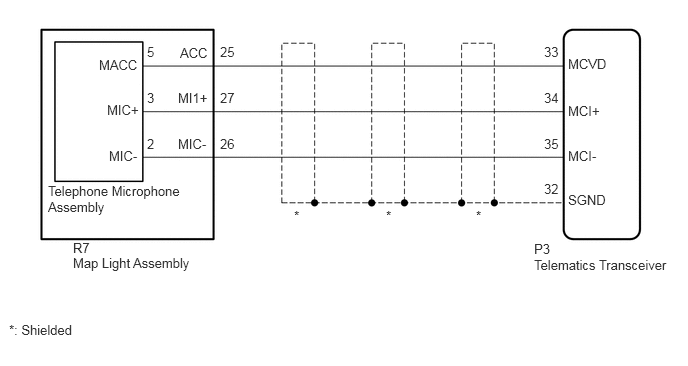
WIRING DIAGRAM

E354791E01
5.563,2.677 7.042,2.896 1.479,0.219 10 false Telematics Transceiver 5.563,2.51 6.042,2.729 0.479,0.219 10 false P3 5.917,0.583 6.396,0.802 0.479,0.219 10 false MCVD 5.917,1.073 6.396,1.292 0.479,0.219 10 false MCI+ 5.917,1.542 6.396,1.76 0.479,0.219 10 false MCI- 5.917,2 6.396,2.219 0.479,0.219 10 false SGND 1.875,0.469 2.354,0.688 0.479,0.219 10 false ACC 1.854,0.938 2.333,1.156 0.479,0.219 10 false MI1+ 1.854,1.417 2.333,1.635 0.479,0.219 10 false MIC- 0.5,1.906 1.948,2.281 1.448,0.375 10 false Telephone Microphone Assembly 0.76,2.5 1.24,2.719 0.479,0.219 10 false R7 0.76,2.656 2.323,2.875 1.563,0.219 10 false Map Light Assembly 3.063,2.167 3.479,2.385 0.417,0.219 10 false * 4.021,2.167 4.438,2.385 0.417,0.219 10 false * 4.958,2.167 5.375,2.385 0.417,0.219 10 false * 0.094,3.354 1.24,3.573 1.146,0.219 10 false *: Shielded 5.667,0.458 6.146,0.677 0.479,0.219 10 false 33 5.667,0.938 6.146,1.156 0.479,0.219 10 false 34 5.667,1.417 6.146,1.635 0.479,0.219 10 false 35 5.667,1.885 6.146,2.104 0.479,0.219 10 false 32 2.292,0.458 2.771,0.677 0.479,0.219 10 false 25 2.292,0.938 2.771,1.156 0.479,0.219 10 false 27 2.292,1.417 2.771,1.635 0.479,0.219 10 false 26 1.531,0.458 2.01,0.677 0.479,0.219 10 false 5 1.531,0.938 2.01,1.156 0.479,0.219 10 false 3 1.531,1.417 2.01,1.635 0.479,0.219 10 false 2 1.031,0.594 1.51,0.813 0.479,0.219 10 false MACC 1.115,1.063 1.594,1.281 0.479,0.219 10 false MIC+ 1.135,1.542 1.615,1.76 0.479,0.219 10 false MIC-

CAUTION / NOTICE / HINT

NOTICE:

Depending on the parts that are replaced during vehicle inspection or maintenance, performing initialization, registration or calibration may be needed. Refer to Registration for Telematics System.

Click hereAudio / Visual / Telematics>TELEMATICS>TELEMATICS SYSTEM (w/ Telematics Transceiver except G-BOOK)>REGISTRATION


PROCEDURE

1.CHECK FOR DTC
a.

Turn the engine switch off.


b.

Connect the GTS to the DLC3.


c.

Turn the engine switch on (IG) and wait for 20 seconds.


d.

Turn the GTS on.


e.

Check for DTCs and check that no DTCs are output.

Click hereAudio / Visual / Telematics>TELEMATICS>TELEMATICS SYSTEM (w/ Telematics Transceiver except G-BOOK)>DTC CHECK / CLEAR

OK:

No DTCs are output.


Result:
Proceed to
OK
NG


OK

NG

2.CHECK HARNESS AND CONNECTOR (TELEMATICS TRANSCEIVER - MAP LIGHT ASSEMBLY (TELEPHONE MICROPHONE ASSEMBLY))
a.

Disconnect the P3 telematics transceiver connector.


b.

Disconnect the R7 map light assembly (telephone microphone assembly) connector.


c.

Measure the resistance according to the value(s) in the table below.

Standard Resistance:
Tester Connection Condition Specified Condition
P3-33 (MCVD) - R7-25 (ACC) Always Below 1 Ω
P3-33 (MCVD) or R7-25 (ACC) - Body ground Always 10 kΩ or higher
P3-34 (MCI+) - R7-27 (MI1+) Always Below 1 Ω
P3-34 (MCI+) or R7-27 (MI1+) - Body ground Always 10 kΩ or higher
P3-35 (MCI-) - R7-26 (MIC-) Always Below 1 Ω
P3-35 (MCI-) or R7-26 (MIC-) - Body ground Always 10 kΩ or higher
P3-32 (SGND) - Body ground Always 10 kΩ or higher


Result:
Proceed to
OK
NG


OK

3.INSPECT MAP LIGHT ASSEMBLY

NG

REPAIR OR REPLACE HARNESS OR CONNECTOR

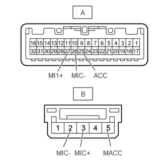
3.INSPECT MAP LIGHT ASSEMBLY
a.
E356115C02
1.521,1.813 1.917,2.073 0.396,0.26 1.51,0.125 1.906,0.385 0.396,0.26 1.313,3.042 1.469,2.677 true 1.667,3.042 1.719,2.698 true 2.292,3.031 2.219,2.698 true 1.198,1.479 1.406,1.083 true 1.969,1.458 1.698,1.073 true 1.583,1.469 1.563,1.083 true 1.167,3.083 1.563,3.26 0.396,0.177 10 false MIC- 1.542,3.083 1.938,3.26 0.396,0.177 10 false MIC+ 2.135,3.083 2.531,3.26 0.396,0.177 10 false MACC 1,1.479 1.354,1.646 0.354,0.167 10 false MI1+ 1.938,1.479 2.292,1.646 0.354,0.167 10 false ACC 1.479,1.479 1.833,1.646 0.354,0.167 10 false MIC- 1.677,1.865 1.833,2.063 0.156,0.198 10 false B 1.667,0.177 1.823,0.375 0.156,0.198 10 false A
*a Component without harness connected
(Map Light Assembly)


Remove the map light assembly.

Click hereVehicle Interior>LIGHTING (INT)>ROOM LIGHT(for Front)>REMOVAL


b.

Remove the telephone microphone assembly.

Click hereAudio / Visual / Telematics>AUDIO / VIDEO>MICROPHONE AMPLIFIER>REMOVAL


c.

Measure the resistance according to the value(s) in the table below.

Standard Resistance:
Tester Connection Condition Specified Condition
A-25 (ACC) - B-5 (MACC) Always Below 1 Ω
A-26 (MI1+) - B-3 (MIC+) Always Below 1 Ω
A-27 (MIC-) - B-2 (MIC-) Always Below 1 Ω
A-25 (ACC) - A-26 (MI1+) Always 10 kΩ or higher
A-25 (ACC) - A-27 (MCO-) Always 10 kΩ or higher
A-26 (MI1+) - A-27 (MCO-) Always 10 kΩ or higher


Result:
Proceed to
OK
NG


OK

4.CHECK TELEPHONE MICROPHONE ASSEMBLY

NG

4.CHECK TELEPHONE MICROPHONE ASSEMBLY
a.

Replace the telephone microphone assembly with a new or known good one.

Click hereAudio / Visual / Telematics>AUDIO / VIDEO>MICROPHONE AMPLIFIER>REMOVAL


c.

Check for DTCs and check that no DTCs are output.

OK:

No DTCs are output.


Result:
Proceed to
OK
NG


OK

END (TELEPHONE MICROPHONE ASSEMBLY IS DEFECTIVE)

NG

5.REPLACE TELEMATICS TRANSCEIVER
a.

Replace the telematics transceiver with a new one.

Click hereAudio / Visual / Telematics>TELEMATICS>TELEMATICS TRANSCEIVER>REMOVAL


Result:
Proceed to
NEXT


NEXT