RM2660E
_51
Engine / Hybrid System
_052787
3UR-FE EMISSION CONTROL
_0327529
AIR SWITCHING VALVE(w/ Secondary Air Injection System)
G
3UR-FE EMISSION CONTROL AIR SWITCHING VALVE(w/ Secondary Air Injection System) INSPECTION
PROCEDURE

 25720
1.INSPECT AIR SWITCHING VALVE ASSEMBLY
a.
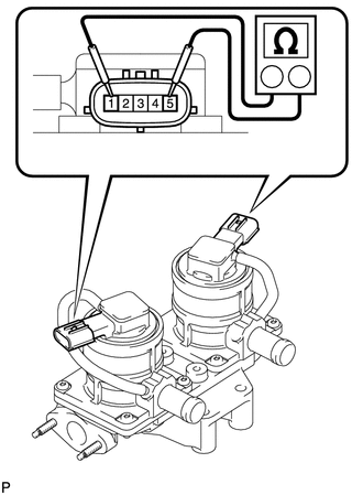
Measure the resistance according to the value(s) in the table below.
- Standard Resistance:
Tester Connection Condition Specified Condition 1 - 5 20°C (68°F) 4.5 to 5.5 Ω 1 - Body ground Always 1 MΩ or higher 5 - Body ground
- NOTICE:
-
When measuring the resistance, do not touch terminals 2, 3 and 4.
If the result is not as specified, replace the air switching valve assembly.
b.
0.781,2.615 0.781,3.01
false
1.875,2.448 1.875,3.073
false
2.729,1.906 2.729,2.552
false
2.771,1.406 3.094,1.406
false
2.146,2.667 2.385,2.927
0.24,0.26
10
false
*a
2.927,2.052 3.167,2.271
0.24,0.219
10
false
*a
1.854,3.104 2.01,3.271
0.156,0.167
10
false
A
0.76,3.031 0.917,3.198
0.156,0.167
10
false
B
3.167,1.313 3.323,1.479
0.156,0.167
10
false
B
2.677,2.563 2.833,2.729
0.156,0.167
10
false
A
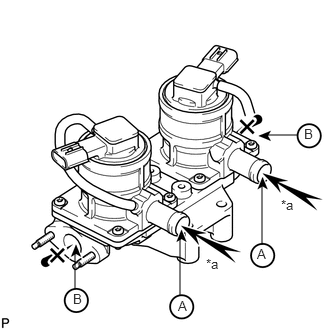
Check the operation of the air switching valve.
i.
Check that air does not flow from port A to port B.
| *a | Air |
- NOTICE:
-
Make sure the applied pressure is 30 kPa (0.3 kgf/cm2, 4.4 psi) or less
If the result is not as specified, replace the air switching valve assembly.
ii.
0.76,4.219 0.76,4.385
false
1.854,4.052 1.854,4.385
false
2.698,3.479 2.698,3.823
false
2.802,3 2.969,3
false
2.875,3.594 3.094,3.813
0.219,0.219
10
false
*a
2.135,4.208 2.375,4.417
0.24,0.208
10
false
*a
1.823,4.406 1.979,4.573
0.156,0.167
10
false
A
0.729,4.438 0.885,4.604
0.156,0.167
10
false
B
2.646,3.854 2.802,4.021
0.156,0.167
10
false
A
3.063,2.917 3.219,3.083
0.156,0.167
10
false
B
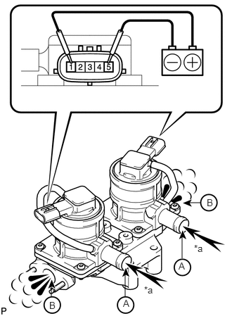
Apply battery voltage to the connector, and check the air switching valve operation.
- OK:
Measurement Condition Specified Condition Battery positive (+) → Terminal 1
Battery negative (-) → Terminal 5Air flows from port A to port B
| *a | Air |
- NOTICE:
-
When applying voltage, do not touch terminals 2, 3 and 4.
If the result is not as specified, replace the air switching valve assembly.