RM2660E
_51
Engine / Hybrid System
_052787
3UR-FE EMISSION CONTROL
_0327533
EMISSION CONTROL SYSTEM(w/ Secondary Air Injection System)
U
3UR-FE EMISSION CONTROL EMISSION CONTROL SYSTEM(w/ Secondary Air Injection System) SYSTEM DIAGRAM
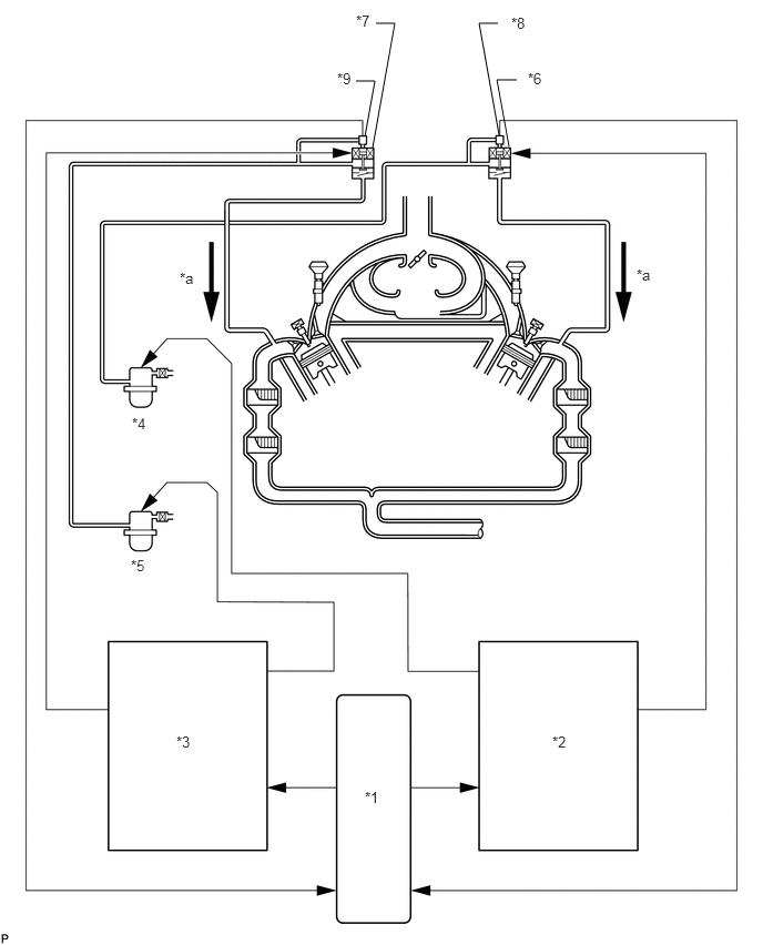
SECONDARY AIR INJECTION CONTROL SYSTEM DIAGRAM
3.5,1.385 3.708,0.219
3.708,0.219 3.531,0.219
false
3.427,1.281 3.521,0.76
3.521,0.76 3.344,0.76
false
4.688,1.271 4.5,0.219
4.5,0.219 4.677,0.219
false
4.781,1.375 4.667,0.75
4.667,0.75 4.854,0.75
false
3.427,7.406 3.635,7.625
0.208,0.219
10
false
*1
5.188,6.885 5.396,7.104
0.208,0.219
10
false
*2
1.656,6.885 1.865,7.104
0.208,0.219
10
false
*3
1.24,3.896 1.448,4.115
0.208,0.219
10
false
*4
1.229,5.229 1.438,5.448
0.208,0.219
10
false
*5
4.958,0.656 5.167,0.875
0.208,0.219
10
false
*6
3.344,0.115 3.552,0.333
0.208,0.219
10
false
*7
4.802,0.135 5.01,0.354
0.208,0.219
10
false
*8
3.167,0.656 3.375,0.875
0.208,0.219
10
false
*9
1.688,2.531 1.896,2.75
0.208,0.219
10
false
*a
5.979,2.5 6.188,2.719
0.208,0.219
10
false
*a
| *1 | ECM | *2 | Air Injection Control Driver (for Bank 1) |
| *3 | Air Injection Control Driver (for Bank 2) | *4 | Air Pump (for Bank 1) |
| *5 | Air Pump (for Bank 2) | *6 | Air Switching Valve (for Bank 1) |
| *7 | Air Switching Valve (for Bank 2) | *8 | Pressure Sensor (for Bank 1) |
| *9 | Pressure Sensor (for Bank 2) | - | - |
| *a | Air | - | - |
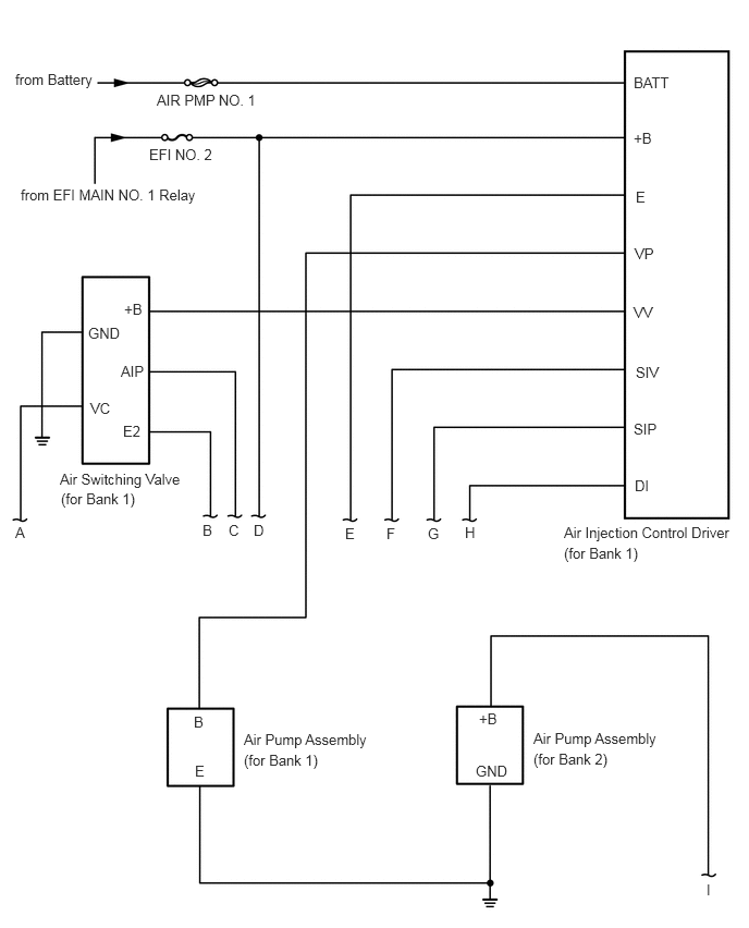
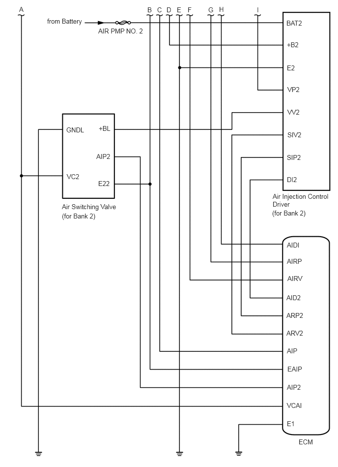
SECONDARY AIR INJECTION SYSTEM WIRING DIAGRAM
0.146,0.677 1.24,0.969
1.094,0.292
10
false
from Battery
1.5,0.875 2.594,1.094
1.094,0.219
10
false
AIR PMP NO. 1
1.427,1.396 2.198,1.667
0.771,0.271
10
false
EFI NO. 2
0.198,1.781 2,2.125
1.802,0.344
10
false
from EFI MAIN NO. 1 Relay
0.573,4.5 1.958,5.146
1.385,0.646
10
false
Air Switching Valve
0.865,3.823 1.177,4.021
0.313,0.198
10
false
VC
4.552,7.292 5.01,7.49
0.458,0.198
10
false
GND
1.188,2.875 1.5,3.073
0.313,0.198
10
false
+B
1.156,3.469 1.615,3.667
0.458,0.198
10
false
AIP
1.177,4.042 1.49,4.24
0.313,0.198
10
false
E2
5.396,5.01 7.104,5.604
1.708,0.594
10
false
Air Injection Control Driver
6.073,4.563 6.385,4.76
0.313,0.198
10
false
DI
6.063,4.021 6.521,4.219
0.458,0.198
10
false
SIP
6.083,3.479 6.542,3.677
0.458,0.198
10
false
SIV
6.063,2.906 6.521,3.104
0.458,0.198
10
false
VV
6.073,2.344 6.531,2.542
0.458,0.198
10
false
VP
6.083,1.802 6.542,2
0.458,0.198
10
false
E
6.063,1.24 6.521,1.438
0.458,0.198
10
false
+B
6.063,0.708 6.521,0.906
0.458,0.198
10
false
BATT
0.146,5.01 0.458,5.208
0.313,0.198
10
false
A
1.938,4.99 2.25,5.188
0.313,0.198
10
false
B
2.188,4.99 2.5,5.188
0.313,0.198
10
false
C
2.427,4.99 2.74,5.188
0.313,0.198
10
false
D
3.302,5.021 3.615,5.219
0.313,0.198
10
false
E
3.698,5.021 4.01,5.219
0.313,0.198
10
false
F
4.094,5.021 4.406,5.219
0.313,0.198
10
false
G
4.448,5.01 4.76,5.208
0.313,0.198
10
false
H
1.854,6.823 2.167,7.021
0.313,0.198
10
false
B
1.865,7.292 2.177,7.49
0.313,0.198
10
false
E
4.583,6.792 4.896,6.99
0.313,0.198
10
false
+B
6.76,8.427 7.073,8.625
0.313,0.198
10
false
I
2.333,6.99 3.76,7.563
1.427,0.573
10
false
Air Pump Assembly
5.104,6.979 6.542,7.552
1.438,0.573
10
false
Air Pump Assembly
0.583,4.688 2.417,4.885
1.833,0.198
10
false
(for Bank 1)
5.396,5.208 6.344,5.521
0.948,0.313
10
false
(for Bank 1)
2.333,7.188 3.281,7.5
0.948,0.313
10
false
(for Bank 1)
5.104,7.177 6.052,7.49
0.948,0.313
10
false
(for Bank 2)
0.844,3.104 1.302,3.302
0.458,0.198
10
false
GND
1,0.365 2.042,0.708
1.042,0.344
10
false
from Battery
2.083,0.573 3.333,0.906
1.25,0.333
10
false
AIR PMP NO. 2
1.406,2.667 2.021,2.865
0.615,0.198
10
false
GNDL
1.417,3.656 1.875,3.854
0.458,0.198
10
false
VC2
2.083,3.802 2.542,4
0.458,0.198
10
false
E22
2.042,3.229 2.656,3.427
0.615,0.198
10
false
AIP2
2.094,2.635 2.708,2.833
0.615,0.198
10
false
+BL
6.073,0.406 6.688,0.604
0.615,0.198
10
false
BAT2
6.083,0.865 6.698,1.063
0.615,0.198
10
false
+B2
6.083,1.354 6.698,1.552
0.615,0.198
10
false
E2
6.094,1.813 6.708,2.01
0.615,0.198
10
false
VP2
6.094,2.292 6.708,2.49
0.615,0.198
10
false
VV2
6.094,2.771 6.708,2.969
0.615,0.198
10
false
SIV2
6.083,3.25 6.698,3.448
0.615,0.198
10
false
SIP2
6.083,3.719 6.698,3.917
0.615,0.198
10
false
DI2
6.073,6.594 6.688,6.792
0.615,0.198
10
false
ARP2
6.083,5.104 6.698,5.302
0.615,0.198
10
false
AIDI
6.083,5.448 6.698,5.646
0.615,0.198
10
false
AIRP
6.094,5.813 6.708,6.01
0.615,0.198
10
false
AIRV
6.073,6.219 6.688,6.417
0.615,0.198
10
false
AID2
6.073,6.969 6.688,7.167
0.615,0.198
10
false
ARV2
6.083,7.344 6.698,7.542
0.615,0.198
10
false
AIP
6.094,7.729 6.708,7.927
0.615,0.198
10
false
EAIP
6.083,8.115 6.698,8.313
0.615,0.198
10
false
AIP2
6.083,8.5 6.698,8.698
0.615,0.198
10
false
VCAI
6.083,8.885 6.698,9.083
0.615,0.198
10
false
E1
6.333,9.271 6.792,9.469
0.458,0.198
10
false
ECM
1.313,4.292 2.719,4.594
1.406,0.302
10
false
Air Switching Valve
5.781,4.073 7.146,4.656
1.365,0.583
10
false
Air Injection Control Driver
1.313,4.49 3.146,4.688
1.833,0.198
10
false
(for Bank 2)
5.771,4.427 6.667,4.76
0.896,0.333
10
false
(for Bank 2)
0.406,0.115 0.563,0.313
0.156,0.198
10
false
A
3.125,0.125 3.281,0.323
0.156,0.198
10
false
B
3.333,0.125 3.49,0.323
0.156,0.198
10
false
C
3.531,0.125 3.688,0.323
0.156,0.198
10
false
D
3.75,0.125 3.906,0.323
0.156,0.198
10
false
E
3.979,0.125 4.135,0.323
0.156,0.198
10
false
F
4.417,0.125 4.573,0.323
0.156,0.198
10
false
G
4.646,0.115 4.802,0.313
0.156,0.198
10
false
H
5.448,0.125 5.604,0.323
0.156,0.198
10
false
I
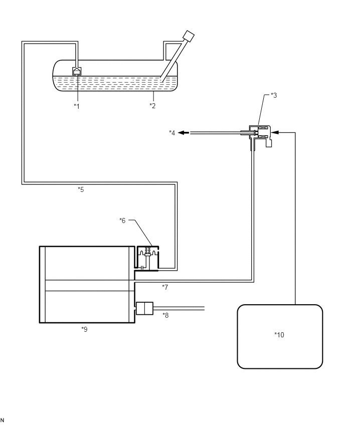
EVAP CONTROL SYSTEM DIAGRAM
1.615,1.552 1.615,2.104
false
3.188,2.104 3.188,1.896
false
5.594,1.969 5.49,1.969
5.49,1.969 5.365,2.594
false
2.667,4.573 2.802,4.573
2.802,4.573 3.167,5.125
false
1.531,2.125 1.771,2.344
0.24,0.219
10
false
*1
3.104,2.115 3.302,2.333
0.198,0.219
10
false
*2
5.625,1.896 5.885,2.115
0.26,0.219
10
false
*3
3.51,2.677 3.688,2.875
0.177,0.198
10
false
*4
5.698,6.875 6.083,7.083
0.385,0.208
10
false
*10
1.615,3.854 1.813,4.052
0.198,0.198
10
false
*5
3.375,6.469 3.604,6.656
0.229,0.188
10
false
*8
3.365,5.885 3.563,6.073
0.198,0.188
10
false
*7
2.479,4.5 2.677,4.698
0.198,0.198
10
false
*6
1.688,6.76 1.875,6.948
0.188,0.188
10
false
*9
| *1 | Fuel Cutoff Valve | *2 | Fuel Tank |
| *3 | Purge VSV | *4 | to Intake Manifold |
| *5 | Vent Line | *6 | Refueling Valve |
| *7 | Purge Line | *8 | Air Inlet Line |
| *9 | Canister | *10 | ECM |
EVAP SYSTEM WIRING DIAGRAM
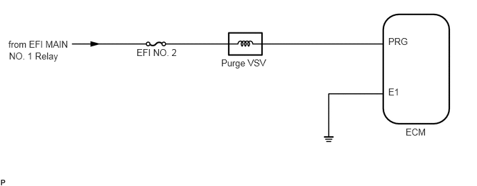
6.094,1.906 6.479,2.073
0.385,0.167
10
false
ECM
5.833,0.542 6.198,0.708
0.365,0.167
10
false
PRG
5.833,1.302 6.083,1.469
0.25,0.167
10
false
E1
2.052,0.708 2.75,0.896
0.698,0.188
10
false
EFI NO. 2
3.323,0.865 4.115,1.052
0.792,0.188
10
false
Purge VSV
0.125,0.583 1.969,1.615
1.844,1.031
10
false
from EFI MAIN
0.135,0.76 1.823,0.958
1.688,0.198
10
false
NO. 1 Relay