V35A-FTS ENGINE CONTROL KNOCK SENSOR INSTALLATION
CAUTION / NOTICE / HINT
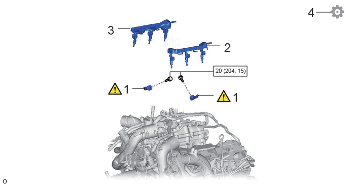
| Procedure | Part Name Code |

|

|

|
|
|---|---|---|---|---|---|
| 1 | KNOCK CONTROL SENSOR | 89615 | ( ) |
- | - |
| 2 | NO. 2 FUEL DELIVERY PIPE SUB-ASSEMBLY LH | 23808B | - | - | - |
| 3 | NO. 2 FUEL DELIVERY PIPE SUB-ASSEMBLY RH | 23807M | - | - | - |
| 4 | PERFORM INITIALIZATION | - | - | - | () |

|
N*m (kgf*cm, ft.*lbf): Specified torque | - | - |
CAUTION / NOTICE / HINT
- NOTICE:
-
This procedure includes the installationl of small-head bolts. Refer to Small-Head Bolts of Basic Repair Hint to identify the small-head bolts.
-
Click hereGeneral>INTRODUCTION>REPAIR INSTRUCTION>PRECAUTION
PROCEDURE

 89615 1.INSTALL KNOCK CONTROL SENSOR
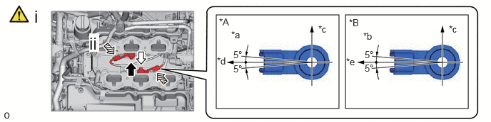
| *A | for Bank 1 | *B | for Bank 2 |
| *a | View A | *b | View B |
| *c | Top | *d | Engine Front |
| *e | Engine Rear | - | - |

|
View A |

|
View B |
Install the 2 knock control sensors with the 2 bolts so that the knock control sensor installation position is as shown in the illustration.
- Torque:
- 20 N*m (204 kgf*cm, 15 ft.*lbf)
- NOTICE:
-
·
Make sure that each knock control sensor is in the correct position.
·If a knock control sensor has been struck or dropped, replace it.
·Make sure that the knock control sensor is in the correct position.
Connect the 2 knock control sensor connectors.
23808B 2.INSTALL NO. 2 FUEL DELIVERY PIPE SUB-ASSEMBLY LH
23807M 3.INSTALL NO. 2 FUEL DELIVERY PIPE SUB-ASSEMBLY RH
4.PERFORM INITIALIZATION
Perform "Inspection After Repair" after replacing the knock control sensor.
Click hereEngine / Hybrid System>V35A-FTS (ENGINE CONTROL)>SFI SYSTEM>INITIALIZATION