RM38G0E _51 Engine / Hybrid System _100527 1GR-FE ENGINE CONTROL _0467388 KNOCK SENSOR A
1GR-FE ENGINE CONTROL KNOCK SENSOR INSTALLATION
CAUTION / NOTICE / HINT
COMPONENTS (INSTALLATION)
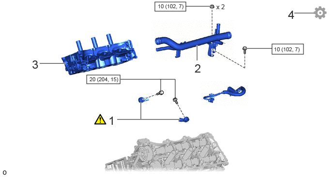
1.865,1.615 2.583,1.802 0.719,0.188 5.854,0.948 6.531,1.167 0.677,0.219 3.333,0.042 4,0.24 0.667,0.198 0.854,1.365 1.417,1.365 true 2.521,2.573 3.875,2.573 true 1.854,4.396 3.417,4.396 true 2.604,4.021 2.604,4.385 true 6.333,0.281 6.781,0.281 true 3.458,1.708 3.458,1.958 true 2.594,1.708 3.771,1.708 3.771,1.708 3.771,2.125 false 5.302,1.042 5.854,1.042 true 3.031,2.198 3.031,2.563 true 4.24,0.969 4.24,1.302 true 4,0.135 4.531,0.135 true 0.688,1.24 0.969,1.594 0.281,0.354 18 false 3 4.188,1.323 4.469,1.677 0.281,0.354 18 false 2 1.667,4.292 1.948,4.646 0.281,0.354 18 false 1 4.656,0.063 4.938,0.417 0.281,0.354 10 false x 2 6.198,0.167 6.479,0.521 0.281,0.354 18 false 4 1.927,1.635 3.219,2.031 1.292,0.396 8 false 20 (204, 15) 5.896,0.99 6.729,1.344 0.833,0.354 8 false 10 (102, 7) 2.333,2.448 2.615,2.802 0.281,0.354 18 false 1 3.396,0.063 4.229,0.417 0.833,0.354 8 false 10 (102, 7)
| Procedure | Part Name Code |

|

|

|
|
|---|---|---|---|---|---|
| 1 | KNOCK CONTROL SENSOR | 89615 | ( ) |
- | |
| 2 | NO. 1 WATER OUTLET PIPE | 16332 | - | - | - |
| 3 | CYLINDER HEAD SUB-ASSEMBLY | 11101 | - | - | - |
| 4 | PERFORM INITIALIZATION | - | - | - | () |

|
N*m (kgf*cm, ft.*lbf): Specified torque | - | - |
PROCEDURE

 89615 1.INSTALL KNOCK CONTROL SENSOR
a.
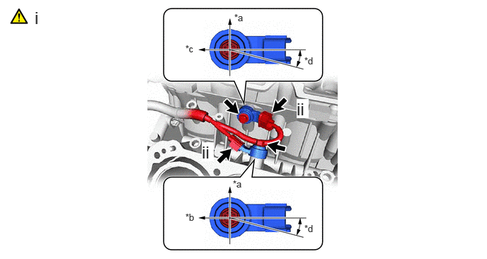
3.448,0.177 3.76,0.333 0.313,0.156 10 false *a 3.427,2.625 3.74,2.781 0.313,0.156 10 false *a 2.729,3.115 3.042,3.271 0.313,0.156 10 false *b 2.729,0.635 3.042,0.792 0.313,0.156 10 false *c 4.479,3.281 4.792,3.438 0.313,0.156 10 false *d 4.479,0.813 4.792,0.969 0.313,0.156 10 false *d 0.51,0.115 0.958,0.5 0.448,0.385 18 false i 4.365,1.458 4.542,1.74 0.177,0.281 18 true ii 2.969,2.094 3.146,2.375 0.177,0.281 18 true ii
| *a | Upper side | *b | Front side |
| *c | Rear side | *d | 15° |
i.
Install the 2 knock control sensors with the 2 bolts as shown in the illustration.
- Torque:
- 20 N*m (204 kgf*cm, 15 ft.*lbf)
ii.
Connect the 2 knock control sensor connectors.
16332 2.INSTALL NO. 1 WATER OUTLET PIPE
- Torque:
- 10 N*m (102 kgf*cm, 7 ft.*lbf)
11101 3.INSTALL CYLINDER HEAD SUB-ASSEMBLY
4.PERFORM INITIALIZATION
a.
Perform "Inspection After Repair" after replacing the knock control sensor.
Click hereEngine / Hybrid System>1GR-FE (ENGINE CONTROL)>SFI SYSTEM>INITIALIZATION