JF2BM TRANSFER / 4WD / AWD TRANSFER SYSTEM P17EE11 4WD/AWD Front Differential Unit Actuator "A" Position Sensor "A" Circuit Circuit Short to Ground P17EE15 4WD/AWD Front Differential Unit Actuator "A" Position Sensor "A" Circuit Circuit Short to Battery or Open P17EF1C 4WD/AWD Front Differential Unit Actuator "A" Position Sensor "A" Circuit Voltage Out of Range
DESCRIPTION
| DTC No. | Detection Item | DTC Detection Condition | Trouble Area | DTC Output from |
|---|---|---|---|---|
| P17EE11 | 4WD/AWD Front Differential Unit Actuator "A" Position Sensor "A" Circuit Circuit Short to Ground |
Diagnosis Condition:
·
Always
Malfunction Status:
·
Front differential lock position sensor output voltage is less than malfunction detection voltage
Malfunction Time:
·
1 second or more
Number of Trips:
·
1 trip |
·
Wire harness and connector
·
Front differential lock position sensor (No. 1 4 wheel drive position switch)
·
4 wheel drive control ECU |
Four Wheel Drive |
| P17EE15 | 4WD/AWD Front Differential Unit Actuator "A" Position Sensor "A" Circuit Circuit Short to Battery or Open |
Diagnosis Condition:
·
Always
Malfunction Status:
·
Front differential lock position sensor output voltage exceeds malfunction detection voltage
Malfunction Time:
·
1 second or more
Number of Trips:
·
1 trip |
·
Wire harness and connector
·
Front differential lock position sensor (No. 1 4 wheel drive position switch)
·
4 wheel drive control ECU |
Four Wheel Drive |
| P17EF1C | 4WD/AWD Front Differential Unit Actuator "A" Position Sensor "A" Circuit Voltage Out of Range |
Diagnosis Condition:
·
Always
Malfunction Status:
·
Position sensor power source monitor voltage is outside range of 4.6 to 5.4 V
Malfunction Time:
·
1 second or more
Number of Trips:
·
1 trip |
·
Wire harness and connector
·
Front differential lock position sensor (No. 1 4 wheel drive position switch)
·
4 wheel drive control ECU |
Four Wheel Drive |
WIRING DIAGRAM
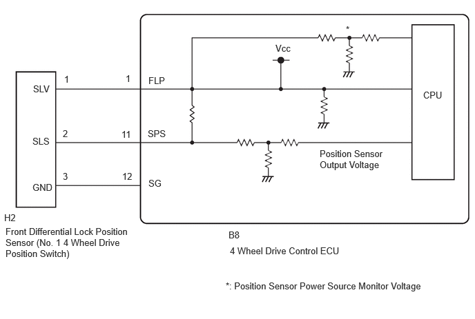
PROCEDURE
Disconnect the B8 4 wheel drive control ECU connector.
Disconnect the H2 front differential lock position sensor (No. 1 4 wheel drive position switch) connector.
Measure the voltage according to the value(s) in the table below.
- Standard Voltage:
-
Tester Connection Condition Specified Condition Click Location & Routing(B8,H2)Location & Routingewd_type=routing;type=c,c;code=B8,H2
Click Connector(B8)Instrument Panel>Engine Room Main Wire / Heater Blower Wire>4 Wheel Drive Control ECUewd_type=component;type=c;code=B8;pinno=11
Click Connector(H2)Engine Compartment>Differential Wire>Differential Position Switch (Front Differential Assembly)ewd_type=component;type=c;code=H2;pinno=2
B8-11 (SPS) or H2-2 (SLS) - Body ground Ignitin switch off Below 1.5 V B8-11 (SPS) or H2-2 (SLS) - Body ground Ignitin switch ON Below 1.5 V
Connect the H2 front differential lock position sensor (No. 1 4 wheel drive position switch) connector.
Connect the B8 4 wheel drive control ECU connector.
- Result:
-
Proceed to OK NG
OK
NG
Disconnect the B8 4 wheel drive control ECU connector.
Disconnect the H2 front differential lock position sensor (No. 1 4 wheel drive position switch) connector.
Measure the resistance according to the value(s) in the table below.
- Standard Resistance:
-
Tester Connection Condition Specified Condition Click Location & Routing(B8,H2)Location & Routingewd_type=routing;type=c,c;code=B8,H2
Click Connector(B8)Instrument Panel>Engine Room Main Wire / Heater Blower Wire>4 Wheel Drive Control ECUewd_type=component;type=c;code=B8;pinno=1,11,12
Click Connector(H2)Engine Compartment>Differential Wire>Differential Position Switch (Front Differential Assembly)ewd_type=component;type=c;code=H2;pinno=1,2,3
B8-1 (FLP) - H2-1 (SLV) Always Below 1 Ω B8-11 (SPS) - H2-2 (SLS) Always Below 1 Ω B8-12 (SG) - H2-3 (GND) Always Below 1 Ω B8-1 (FLP) or H2-1 (SLV) - Body ground Always 10 kΩ or higher B8-11 (SPS) or H2-2 (SLS) - Body ground Always 10 kΩ or higher
Connect the H2 front differential lock position sensor (No. 1 4 wheel drive position switch) connector.
Connect the B8 4 wheel drive control ECU connector.
- Result:
-
Proceed to OK NG
OK
NG
Disconnect the H2 front differential lock position sensor (No. 1 4 wheel drive position switch) connector.
Measure the voltage according to the value(s) in the table below.
- Standard Voltage:
-
Tester Connection Switch Condition Specified Condition Click Location & Routing(H2)Location & Routingewd_type=routing;type=c;code=H2
Click Connector(H2)Engine Compartment>Differential Wire>Differential Position Switch (Front Differential Assembly)ewd_type=component;type=c;code=H2;pinno=1
H2-1 (SLV) - Body ground Ignition switch ON 4.6 to 5.4 V
Connect the H2 front differential lock position sensor (No. 1 4 wheel drive position switch) connector.
- Result:
-
Proceed to OK NG
OK
NG
for LHD: Click hereDrivetrain>JF2BM (TRANSFER / 4WD / AWD)>4WD CONTROL ECU (for LHD)>REMOVAL
for RHD: Click hereDrivetrain>JF2BM (TRANSFER / 4WD / AWD)>4WD CONTROL ECU (for RHD)>REMOVAL
Turn the ignition switch off.
Remove the front differential lock position sensor (No. 1 4 wheel drive position switch).
Connect 3 1.5 V dry batteries in series.
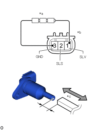
| *a | Dry Batteries |
| *b | Component without harness connected (Front Differential Lock Position Sensor (No. 1 4 Wheel Drive Position Switch)) |
| *c | Piece of Metal |
Connect terminal 1 (SLV) to the batteries positive (+) terminal, and terminal 3 (GND) to the batteries negative (-) terminal.
Move a piece of metal close to the edge of the front differential lock position sensor (No. 1 4 wheel drive position switch), and then move it away and check that the resistance changes.
Measure the resistance according to the value(s) in the table below.
- Standard Resistance:
-
Tester Connection Condition Specified Condition 2 (SLS) - 3 (GND) Low (Move piece of metal away) 300 to 400 Ω 2 (SLS) - 3 (GND) High (Move piece of metal closer) 2.2k to 2.4k Ω
Install the front differential lock position sensor (No. 1 4 wheel drive position switch).
- Result:
-
Proceed to OK NG
OK
for LHD: Click hereDrivetrain>JF2BM (TRANSFER / 4WD / AWD)>4WD CONTROL ECU (for LHD)>REMOVAL
for RHD: Click hereDrivetrain>JF2BM (TRANSFER / 4WD / AWD)>4WD CONTROL ECU (for RHD)>REMOVAL
NG