SEAT REAR POWER SEAT CONTROL SYSTEM Park / Neutral Position Switch Circuit
DESCRIPTION
The fold seat control ECU receives signals from the main body ECU (multiplex network body ECU) and controls the seat folding and return operations. If the shift lever is in any position other than P when the ignition switch is ON, the seat cannot be operated.
WIRING DIAGRAM
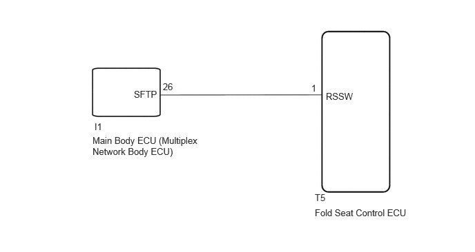
PROCEDURE
Read the Data List according to the display on the GTS. (for V35A-FTS)
- Powertrain > Transmission > Data List
-
Tester Display Measurement Item Range Normal Condition Diagnostic Note Shift SW Status (P Range) Shift position P signal ON or OFF ON: Shift lever in P
OFF: Shift lever not in P-
- Powertrain > Transmission > Data List
-
Tester Display Shift SW Status (P Range) - 50003 373 15
Read the Data List according to the display on the GTS. (for 1GR-FE)
- Powertrain > Engine > Data List
-
Tester Display Measurement Item Range Normal Condition Diagnostic Note Shift SW Status (P Range) Shift position P signal ON or OFF ON: Shift lever in P
OFF: Shift lever not in P-
- Powertrain > Engine > Data List
-
Tester Display Shift SW Status (P Range) - 50003 372 15
- Result:
-
Proceed to OK NG
OK
NG
for 1GR-FE: Click hereDrivetrain>AC60F (AUTOMATIC TRANSMISSION / TRANSAXLE)>AUTOMATIC TRANSMISSION SYSTEM>HOW TO PROCEED WITH TROUBLESHOOTING
for V35A-FTS: Click hereDrivetrain>AJA0F (AUTOMATIC TRANSMISSION / TRANSAXLE)>AUTOMATIC TRANSMISSION SYSTEM (for V35A-FTS)>HOW TO PROCEED WITH TROUBLESHOOTING
Disconnect the T5 fold seat control ECU connector.
Disconnect the I1 main body ECU (multiplex network body ECU) connector.
Measure the resistance according to the value(s) in the table below.
- Standard Resistance:
-
Tester Connection Condition Specified Condition Click Location & Routing(T5,I1)Location & Routingewd_type=routing;type=c,c;code=T5,I1
Click Connector(T5)Body>No. 3 Floor Wire / Theft Warning Sensor Cord Sub-Assembly>Fold Seat Control ECUewd_type=component;type=c;code=T5;pinno=1
T5-1 (RSSW) - I1-26 (SFTP) Always Below 1 Ω T5-1 (RSSW) - I1-26 (SFTP) Always 10 kΩ or higher
- Result:
-
Proceed to OK NG
OK
NG
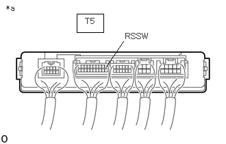
| *a | Component with harness connected (Fold Seat Control ECU) |
Remove the fold seat control ECU with its connectors still connected.
Click hereVehicle Interior>SEAT>POWER SEAT CONTROL ECU (for Rear No. 2 Seat)>REMOVAL
Measure the voltage according to the value(s) in the table below.
- Standard Voltage:
-
Tester Connection Condition Specified Condition Click Location & Routing(T5)Location & Routingewd_type=routing;type=c;code=T5
Click Connector(T5)Body>No. 3 Floor Wire / Theft Warning Sensor Cord Sub-Assembly>Fold Seat Control ECUewd_type=component;type=c;code=T5;pinno=1
T5-1 (RSSW) - Body ground Ignition switch ACC or ON
Shift lever in P11 to 14 V
- Result:
-
Proceed to OK NG
OK
NG
| *a | Component with harness connected (Fold Seat Control ECU) |
Remove the fold seat control ECU with its connectors still connected.
Click hereVehicle Interior>SEAT>POWER SEAT CONTROL ECU (for Rear No. 2 Seat)>REMOVAL
Measure the voltage according to the value(s) in the table below.
- Standard Voltage:
-
Tester Connection Condition Specified Condition Click Location & Routing(T5)Location & Routingewd_type=routing;type=c;code=T5
Click Connector(T5)Body>No. 3 Floor Wire / Theft Warning Sensor Cord Sub-Assembly>Fold Seat Control ECUewd_type=component;type=c;code=T5;pinno=1
T5-1 (RSSW) - Body ground Ignition switch ACC or ON
Shift lever in P11 to 14 V T5-1 (RSSW) - Body ground Ignition switch ACC or ON
Shift lever not in PBelow 1 V
- Result:
-
Proceed to OK NG
OK
NG
for LHD: Click herePower Source / Network>POWER DISTRIBUTION>MAIN BODY ECU (for LHD)>REMOVAL
for RHD: Click herePower Source / Network>POWER DISTRIBUTION>MAIN BODY ECU (for RHD)>REMOVAL