RM38G0E _56 Audio / Visual / Telematics _100606 AUDIO / VIDEO _0467500 ACTIVE NOISE CONTROL SYSTEM(for Type B) U
AUDIO / VIDEO ACTIVE NOISE CONTROL SYSTEM(for Type B) TERMINALS OF ECU
CHECK STEREO COMPONENT EQUALIZER ASSEMBLY
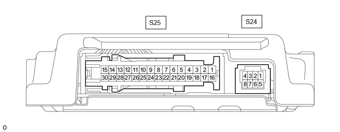
3.073,0.344 3.5,0.615 0.427,0.271 5.094,0.323 5.521,0.594 0.427,0.271 3.146,0.396 3.5,0.542 0.354,0.146 10 false S25 5.177,0.375 5.531,0.521 0.354,0.146 10 false S24
| Terminal No. (Symbol) | Terminal Description | Condition | Specified Condition |
|---|---|---|---|
|
*1: w/ Telematics Transceiver *2: w/ Audio and Visual System |
|||
| S25-4(TMUT) - S25-30(GND)*1 | Mute signal | Audio system playing | 3 to 5 V |
| Emergency call mode | Below 1 V | ||
| S25-15(+B) - S25-30(GND) | Power source | Always | 11 to 14 V |
| S25-29(IGP) - S25-30(GND) | Power source (IG) | Ignition switch ON | 11 to 14 V |
| S25-14(ACC) - S25-30(GND) | Power source (ACC) | Ignition switch ACC | 11 to 14 V |
| S25-3(NEI) - S25-30(GND) | Engine pulse signal | Idling with warm engine | Pulse generation (See waveform 1) |
| S25-8(FRI+)*2 | Sound signal (Front Right) | Audio system playing | A waveform synchronized with sound signals is output |
| S25-23(FRI-)*2 | Sound signal (Front Right) | Audio system playing | A waveform synchronized with sound signals is output |
| S25-9(FLI+)*2 | Sound signal (Front Left) | Audio system playing | A waveform synchronized with sound signals is output |
| S25-24(FLI-)*2 | Sound signal (Front Left) | Audio system playing | A waveform synchronized with sound signals is output |
| S25-7(ASG1)*2 | Shield ground | - | - |
| S25-19(TMU1)*1*2 | Mute signal | Audio system playing | 3 to 5 V |
| Emergency call mode | Below 1 V | ||
| S25-12(FR+) - S25-30(GND) | Sound signal (Front Right) | Audio system playing | A waveform synchronized with sound signals is output |
| S25-27(FR-) - S25-30(GND) | Sound signal (Front Right) | Audio system playing | A waveform synchronized with sound signals is output |
| S25-13(FL+) - S25-30(GND) | Sound signal (Front Left) | Audio system playing | A waveform synchronized with sound signals is output |
| S25-28(FL-) - S25-30(GND) | Sound signal (Front Left) | Audio system playing | A waveform synchronized with sound signals is output |
| S25-11(RL+) - S25-30(GND) | Sound signal (Rear Left) | Audio system playing | A waveform synchronized with sound signals is output |
| S25-26(RL-) - S25-30(GND) | Sound signal (Rear Left) | Audio system playing | A waveform synchronized with sound signals is output |
| S25-1(CANH) | CAN communication signal | - | - |
| S25-16(CANL) | CAN communication signal | - | - |
| S24-1(MC1+) - S25-30(GND) | Active noise control microphone input signal | No. 1 active noise control microphone tapped with finger | Pulse generation |
| S24-5(MC1-) - S25-30(GND) | Active noise control microphone input signal | Always | Below 1 Ω |
| S24-2(MC2+) - S25-30(GND) | Active noise control microphone input signal | No. 2 active noise control microphone tapped with finger | Pulse generation |
| S24-6(MC2-) - S25-30(GND) | Active noise control microphone input signal | Always | Below 1 Ω |
| S24-3(MC3+) - S25-30(GND) | Active noise control microphone input signal | No. 3 active noise control microphone tapped with finger | Pulse generation |
| S24-7(MC3-) - S25-30(GND) | Active noise control microphone input signal | Always | Below 1 Ω |
| S24-4(MC4+) - S25-30(GND) | Active noise control microphone input signal | No. 4 active noise control microphone tapped with finger | Pulse generation |
| S24-8(MC4-) - S25-30(GND) | Active noise control microphone input signal | Always | Below 1 Ω |
a.
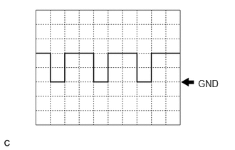
Waveform 1
- HINT:
-
 2.896,1.135 3.313,1.271 0.417,0.135 10 false GND
-
The oscilloscope waveform shown in the illustration is an example for reference only. The waveform fluctuates according to engine speed.
| Item | Condition |
|---|---|
| Measurement terminal | S25-3 (NEI) - S25-30 (GND) |
| Tool setting | 5 V/DIV., 20 ms./DIV. |
| Vehicle condition | Idling with warm engine |
RADIO RECEIVER ASSEMBLY (w/ AUDIO AND VISUAL SYSTEM [for Radio Receiver Type])
RADIO AND DISPLAY RECEIVER ASSEMBLY (w/ AUDIO AND VISUAL SYSTEM [for Radio and Display Type, except 12.3 Inch Display])