AUDIO / VIDEO REAR SEAT ENTERTAINMENT SYSTEM Television Display does not Turn ON
DESCRIPTION
The multi-display controller and television display assembly are connected using this power on output signal lines.
Using this circuit, the multi-display controller sends power ON signal to the television display assembly.
WIRING DIAGRAM
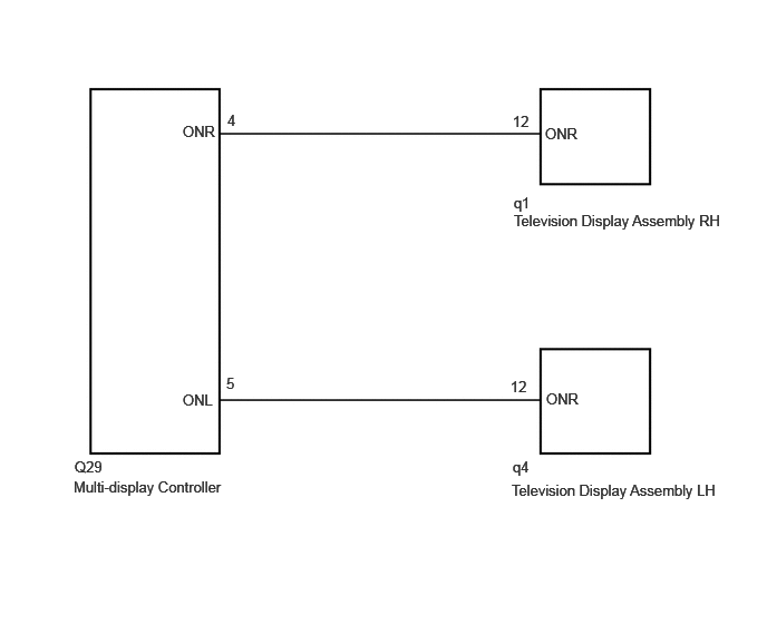
PROCEDURE
Check which television display assembly does not operate.
- Result:
-
Result Proceed to Television display assembly LH does not operate. A Television display assembly RH does not operate. B Television display assembly LH and television display assembly RH does not operate. C
A
B
C
Disconnect the q1 television display assembly RH connector.
Measure the voltage according to the value(s) in the table below.
- Standard Voltage:
-
Tester Connection Switch Condition Specified Condition Click Location & Routing(q1)Location & Routingewd_type=routing;type=c;code=q1
Click Connector(q1)Seat>Seat Audio Wire>Television Display Assembly RHewd_type=component;type=c;code=q1;pinno=12
q1-12 (ONR) - Body ground Ignition switch ACC 4.2 to 5.5 V
- Result:
-
Proceed to OK NG
OK
NG
Disconnect the Q29 multi-display controller connector.
Disconnect the q1 television display assembly RH connector.
Measure the resistance according to the value(s) in the table below.
- Standard Resistance:
-
Tester Connection Condition Specified Condition Click Location & Routing(Q29,q1)Location & Routingewd_type=routing;type=c,c;code=Q29,q1
Click Connector(Q29)Seat>Floor Wire>Multi-Display Controllerewd_type=component;type=c;code=Q29;pinno=4
Click Connector(q1)Seat>Seat Audio Wire>Television Display Assembly RHewd_type=component;type=c;code=q1;pinno=12
Q29-4 (ONR) - q1-12 (ONR) Always Below 1 Ω Q29-4 (ONR) - Body ground Always 10 kΩ or higher
- Result:
-
Proceed to OK NG
OK
Click hereAudio / Visual / Telematics>AUDIO / VIDEO>REAR SEAT ENTERTAINMENT SYSTEM>PROBLEM SYMPTOMS TABLE
NG
Disconnect the q4 television display assembly LH connector.
Measure the voltage according to the value(s) in the table below.
- Standard Voltage:
-
Tester Connection Switch Condition Specified Condition Click Location & Routing(q4)Location & Routingewd_type=routing;type=c;code=q4
Click Connector(q4)Seat>Seat Audio Wire>Television Display Assembly LHewd_type=component;type=c;code=q4;pinno=12
q4-12 (ONR) - Body ground Ignition switch ACC 4.2 to 5.5 V
- Result:
-
Proceed to OK NG
OK
NG
Disconnect the Q29 multi-display controller connector.
Disconnect the q4 television display assembly LH connector.
Measure the resistance according to the value(s) in the table below.
- Standard Resistance:
-
Tester Connection Condition Specified Condition Click Location & Routing(Q29,q4)Location & Routingewd_type=routing;type=c,c;code=Q29,q4
Click Connector(Q29)Seat>Floor Wire>Multi-Display Controllerewd_type=component;type=c;code=Q29;pinno=5
Click Connector(q4)Seat>Seat Audio Wire>Television Display Assembly LHewd_type=component;type=c;code=q4;pinno=12
Q29-5 (ONL) - q4-12 (ONR) Always Below 1 Ω Q29-5 (ONL) - Body ground Always 10 kΩ or higher
- Result:
-
Proceed to OK NG
OK
Click hereAudio / Visual / Telematics>AUDIO / VIDEO>REAR SEAT ENTERTAINMENT SYSTEM>PROBLEM SYMPTOMS TABLE
NG
Disconnect the Q29 multi-display controller connector.
Disconnect the q1 television display assembly RH connector.
Disconnect the q4 television display assembly LH connector.
Measure the resistance according to the value(s) in the table below.
- Standard Resistance:
-
Tester Connection Condition Specified Condition Click Location & Routing(Q29,q1,q4)Location & Routingewd_type=routing;type=c,c,c;code=Q29,q1,q4
Click Connector(Q29)Seat>Floor Wire>Multi-Display Controllerewd_type=component;type=c;code=Q29;pinno=4,5
Click Connector(q1)Seat>Seat Audio Wire>Television Display Assembly RHewd_type=component;type=c;code=q1;pinno=12
Click Connector(q4)Seat>Seat Audio Wire>Television Display Assembly LHewd_type=component;type=c;code=q4;pinno=12
Q29-4 (ONR) - q1-12 (ONR) Always Below 1 Ω Q29-5 (ONL) - q4-12 (ONR) Always Below 1 Ω Q29-4 (ONR) - Body ground Always 10 kΩ or higher Q29-5 (ONL) - Body ground Always 10 kΩ or higher
- Result:
-
Proceed to OK NG
OK
NG