POWER DISTRIBUTION MAIN BODY ECU(for LHD) INSTALLATION
CAUTION / NOTICE / HINT
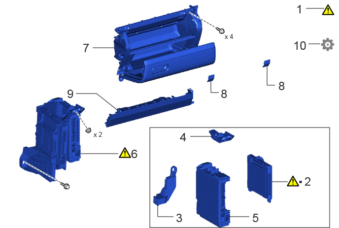
| Procedure | Part Name Code |

|

|

|
|
|---|---|---|---|---|---|
| 1 | PRECAUTION | - | ( ) |
- | - |
| 2 | MAIN BODY ECU (MULTIPLEX NETWORK BODY ECU) | 89221 | () |
- | - |
| 3 | JUNCTION BLOCK BRACKET | 82673B | - | - | - |
| 4 | JUNCTION BLOCK BRACKET | 82673A | - | - | - |
| 5 | POWER DISTRIBUTION BOX ASSEMBLY | 82730G | - | - | - |
| 6 | ECU INTEGRATION BOX RH | 82877 | () |
- | - |
| 7 | LOWER NO. 2 INSTRUMENT PANEL ASSEMBLY | 55320 | - | - | - |
| 8 | INSTRUMENT PANEL BOX DOOR COVER | 55443A | - | - | - |
| 9 | LOWER NO. 2 INSTRUMENT PANEL AIRBAG ASSEMBLY | 73990 | - | - | - |
| 10 | ECU CONFIGURATION | - | - | - | () |
| ● | Non-reusable part | - | - |
CAUTION / NOTICE / HINT
- HINT:
-
A bolt without a torque specification is shown in the standard bolt chart.
-
Click hereGeneral>SPECIFICATIONS>STANDARD BOLT>SPECIFIED TORQUE FOR STANDARD BOLTS
- NOTICE:
-
·
After replacing the MAIN BODY ECU (MULTIPLEX NETWORK BODY ECU), make sure to perform ECU configuration.
·After performing the ECU configuration procedure, make sure to perform the initialization procedure for when the cable has been disconnected and reconnected to the negative (-) auxiliary battery terminal.
PROCEDURE

 1. PRECAUTION
|
|
|
89221 2.INSTALL MAIN BODY ECU (MULTIPLEX NETWORK BODY ECU)
|
|
|
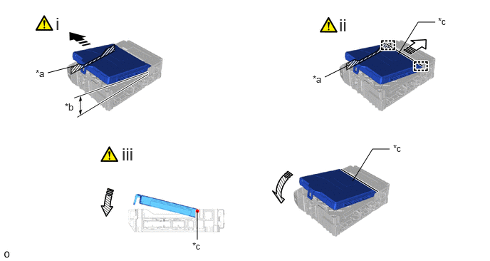
| *a | Housing Sidewall | *b | 20° or more |
| *c | Power Distribution Box Assembly Side A | - | - |

|
Set in this Direction |

|
Slide in this Direction |

|
Install in this Direction | - | - |
Press the main body ECU (multiplex network body ECU) to the housing sidewall as shown in the illustration.
- HINT:
-
Make sure the angle between the power distribution box assembly and the main body ECU (multiplex network body ECU) is 20° or more.
Slide the main body ECU (multiplex network body ECU) along the housing sidewall in the direction of the arrow (power distribution box assembly side A) and insert the guide as shown in the illustration.
- NOTICE:
-
Do not press against the main body ECU (multiplex network body ECU) sidewall too hard.
Rotate the main body ECU (multiplex network body ECU) about its edge which contacts with the power distribution box assembly side A as shown in the illustration.
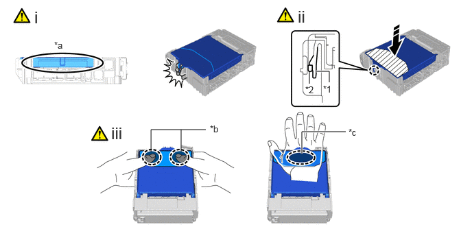
| *1 | Power Distribution Box Assembly | *2 | Main Body ECU (Multiplex Network Body ECU) |
| *a | Before Locking | *b | Press the 2 sides of the main body ECU (multiplex network body ECU) with both hands. |
| *c | Press the center of the main body ECU (multiplex network body ECU) with one hand. | - | - |

|
Place fingers or the palm of your hand here |
|
Install in this Direction |

|
Pressing Area | - | - |
Rotate it until the main body ECU (multiplex network body ECU) enters the lock of the power distribution box assembly.
Press the push area, attach the claw, and install the main body ECU (multiplex network body ECU).
- NOTICE:
-
·
Be sure to press only the push area.
·Do not insert with a force of 98 N (10 kgf, 22.0 lbf) or higher to prevent it from being damaged.
·Check the engagement of the main body ECU (multiplex network body ECU) and the power distribution box assembly by the locking sound.
·Do not put your weight on the main body ECU (multiplex network body ECU) when engaging the main body ECU (multiplex network body ECU) to prevent it from being damaged.
- HINT:
-
If a locking sound cannot be heard, visually check the lock part engagement. Or check that the height of the main body ECU (multiplex network body ECU) and the power distribution box assembly are the same.
Press it in one of the ways as shown in the illustration.
82673B 3.INSTALL JUNCTION BLOCK BRACKET
82673A 4.INSTALL JUNCTION BLOCK BRACKET
82730G 5.INSTALL POWER DISTRIBUTION BOX ASSEMBLY
82877 6.INSTALL ECU INTEGRATION BOX RH
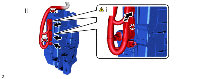
|
|
Install in this Direction | - | - |
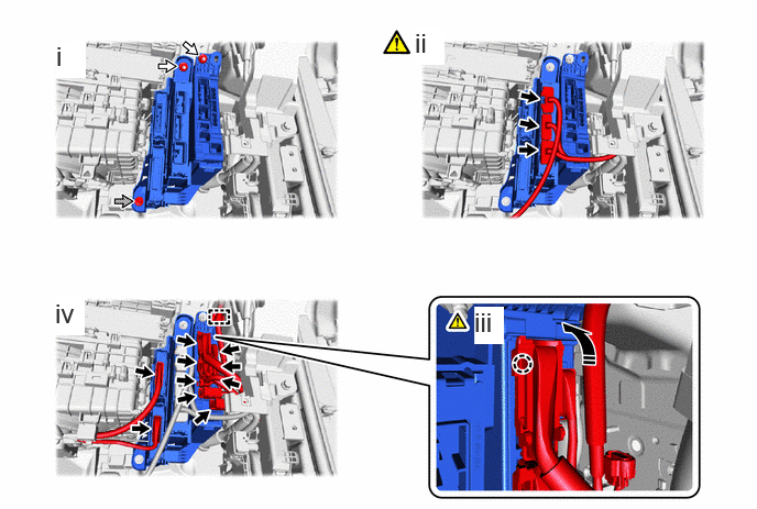
Attach the claw to connect the 2 lever connectors.
- NOTICE:
-
Be sure to connect the lever connector securely.
Connect the connector and attach the clamp.
|
|
Install in this Direction |

|
Connector |

|
Nut |

|
Bolt |
Install the ECU integration box RH with the 2 nuts and bolt.
w/ Stop and Start System:
Connect the 3 connectors.
Attach the claw to connect the lever connector.
- NOTICE:
-
Be sure to connect the lever connector securely.
Connect the 9 connectors and attach the clamp.
55320 7.INSTALL LOWER NO. 2 INSTRUMENT PANEL ASSEMBLY
55443A 8.INSTALL INSTRUMENT PANEL BOX DOOR COVER
73990 9.INSTALL LOWER NO. 2 INSTRUMENT PANEL AIRBAG ASSEMBLY
10. ECU CONFIGURATION