NETWORKING NETWORK GATEWAY ECU(for RHD) INSTALLATION
CAUTION / NOTICE / HINT
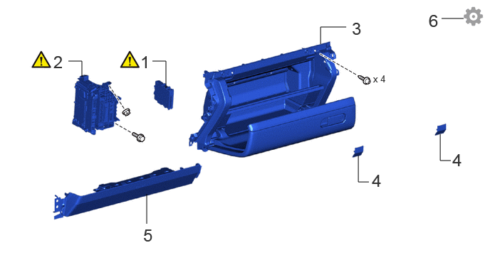
| Procedure | Part Name Code |

|

|

|
|
|---|---|---|---|---|---|
| 1 | NETWORK GATEWAY ECU | 89111 | ( ) |
- | - |
| 2 | ECU INTEGRATION BOX LH | 82878 | () |
- | - |
| 3 | LOWER NO. 2 INSTRUMENT PANEL ASSEMBLY | 55320 | - | - | - |
| 4 | INSTRUMENT PANEL BOX DOOR COVER | 55443A | - | - | - |
| 5 | LOWER NO. 2 INSTRUMENT PANEL AIRBAG ASSEMBLY | 73990 | - | - | - |
| 6 | UPDATE ECU SECURITY KEY | - | - | - | () |
CAUTION / NOTICE / HINT
- HINT:
-
A bolt without a torque specification is shown in the standard bolt chart.
-
Click hereGeneral>SPECIFICATIONS>STANDARD BOLT>SPECIFIED TORQUE FOR STANDARD BOLTS
PROCEDURE

 89111 1.INSTALL NETWORK GATEWAY ECU
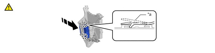
| *a | Retainer | - | - |

|
Install in this Direction | - | - |
Attach the claw and install the network gateway ECU.
- NOTICE:
-
Be sure that the ECU integration box LH is over the retainer of the network gateway ECU as shown in the illustration.
82878 2.INSTALL ECU INTEGRATION BOX LH
|
|
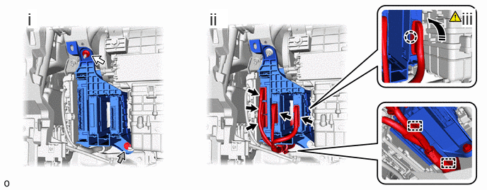
Install in this Direction |

|
Connector |

|
Nut |

|
Bolt |
Install the ECU integration box LH with the nut and bolt.
Attach the clamp and connect the 4 connectors.
Attach the claw to connect the lever connector.
- NOTICE:
-
Be sure to connect the lever connector securely.
55320 3.INSTALL LOWER NO. 2 INSTRUMENT PANEL ASSEMBLY
55443A 4.INSTALL INSTRUMENT PANEL BOX DOOR COVER
73990 5. LOWER NO. 2 INSTRUMENT PANEL AIRBAG ASSEMBLY
6.UPDATE ECU SECURITY KEY