HEATING / AIR CONDITIONING REAR AIR CONDITIONING UNIT REASSEMBLY
CAUTION / NOTICE / HINT
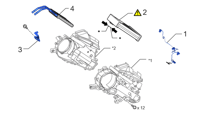
| Procedure | Part Name Code |

|

|

|
|
|---|---|---|---|---|---|
| 1 | NO. 2 COOLER WIRING HARNESS SUB-ASSEMBLY | 88605C | - | - | - |
| 2 | EVAPORATOR SUB-ASSEMBLY (REAR) | 88501R | ( ) |
- | - |
| 3 | HEATER CLAMP | - | - | - | - |
| 4 | HEATER RADIATOR UNIT SUB-ASSEMBLY | 87107B | - | - | - |
| *1 | COOLING UNIT CASE LH | *2 | COOLING UNIT CASE RH |
| ● | Non-reusable part |

|
Compressor oil ND-OIL 8 or equivalent |
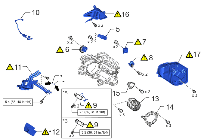
| Procedure | Part Name Code |
|
|
|
|
|---|---|---|---|---|---|
| 5 | REAR NO. 1 AIR CONDITIONING UNIT BRACKET | 88F88G | - | - | - |
| 6 | REAR MODE DAMPER SERVO SUB-ASSEMBLY | 87106X | () |
- | - |
| 7 | NO. 2 AIRMIX DAMPER SERVO SUB-ASSEMBLY | 87106V | () |
- | - |
| 8 | REAR AIRMIX DAMPER SERVO SUB-ASSEMBLY | 87106W | () |
- | - |
| 9 | REAR COOLING UNIT EXPANSION VALVE | 88515B | () |
- | - |
| 10 | NO. 1 COOLER WIRING HARNESS SUB-ASSEMBLY | 88605 | - | - | - |
| 11 | NO. 6 AIR CONDITIONING TUBE AND ACCESSORY ASSEMBLY | 88G10B | () |
- | - |
| 12 | REAR NO. 1 AIR CONDITIONING UNIT PACKING | 88561P | () |
- | - |
| 13 | REAR BLOWER MOTOR WITH FAN SUB-ASSEMBLY | 87103D | - | - | - |
| 14 | HEATER BLOWER COVER | 87236C | - | - | - |
| 15 | BLOWER MOTOR CONTROL | 87165C | - | - | - |
| 16 | REAR NO. 1 SIDE AIR DUCT | 87217D | () |
- | - |
| 17 | REAR NO. 2 SIDE AIR DUCT | 87217E | () |
- | - |
| *A | w/ Magnet Valve | *B | w/o Magnet Valve |

|
N*m (kgf*cm, ft.*lbf): Specified torque | ● | Non-reusable part |
|
|
Compressor oil ND-OIL 8 or equivalent | - | - |
PROCEDURE

 88605C 1.INSTALL NO. 2 COOLER WIRING HARNESS SUB-ASSEMBLY
88501R 2.INSTALL EVAPORATOR SUB-ASSEMBLY (REAR)
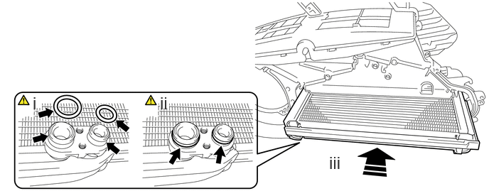

|
Install in this Direction | - | - |
Remove the vinyl tape from the air conditioning tube assembly and then apply a sufficient amount of compressor oil to 2 new O-rings and the fitting surface of the evaporator sub-assembly (rear).
- Compressor Oil:
-
ND-OIL 8 or equivalent
Install the 2 O-rings to the evaporator sub-assembly (rear).
- NOTICE:
-
Keep the O-rings and O-ring fitting surfaces free of foreign matter.
Install the evaporator sub-assembly (rear) as shown in the illustration.
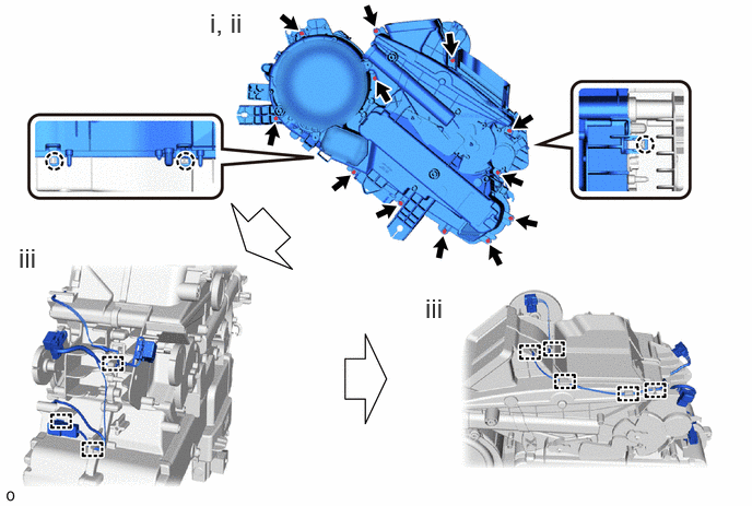
Attach the claw and install the cooling unit case LH.
Install the 12 screws.
Attach the clamp.
3.INSTALL HEATER CLAMP
87107B 4.INSTALL HEATER RADIATOR UNIT SUB-ASSEMBLY
88F88G 5.INSTALL REAR NO. 1 AIR CONDITIONING UNIT BRACKET
87106X 6.INSTALL REAR MODE DAMPER SERVO SUB-ASSEMBLY
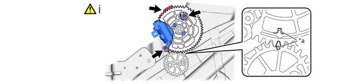
| *a | Reference Point | - | - |
Install the rear mode damper servo sub-assembly.
1. Using the reference points, install the rear mode damper servo sub-assembly with the 2 screws.
2. Connect the connector.
87106V 7.INSTALL NO. 2 AIRMIX DAMPER SERVO SUB-ASSEMBLY
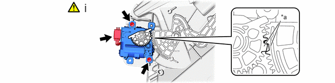
| *a | Reference Point | - | - |
Install the No. 2 airmix damper servo sub-assembly.
1. Using the reference points, install the No. 2 airmix damper servo sub-assembly with the 2 screws.
2. Connect the connector.
87106W 8.INSTALL REAR AIRMIX DAMPER SERVO SUB-ASSEMBLY
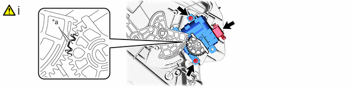
| *a | Reference Point | - | - |
Install the rear airmix damper servo sub-assembly.
1. Using the reference points, install the rear airmix damper servo sub-assembly with the 2 screws.
2. Connect the connector.
88515B 9.INSTALL REAR COOLING UNIT EXPANSION VALVE
w/ Magnet Valve:

Remove the vinyl tape from the rear cooling unit expansion valve.
Using a 4 mm hexagon socket wrench, install the rear cooling unit expansion valve with the 2 hexagon bolts.
- Torque:
- 3.5 N*m (36 kgf*cm, 31 in.*lbf)
Torque:
- NOTICE:
-
Make sure not to cut the O-ring while installing it. (Cut O-rings cannot be installed.)
Attach the clamp.
w/o Magnet Valve:
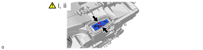
Remove the vinyl tape from the rear cooling unit expansion valve.
Using a 4 mm hexagon socket wrench, install the rear cooling unit expansion valve with the 2 hexagon bolts.
- Torque:
- 3.5 N*m (36 kgf*cm, 31 in.*lbf)
- NOTICE:
-
Make sure not to cut the O-ring while installing it. (Cut O-rings cannot be installed.)
88605 10.INSTALL NO. 1 COOLER WIRING HARNESS SUB-ASSEMBLY
88G10B 11.INSTALL NO. 6 AIR CONDITIONING TUBE AND ACCESSORY ASSEMBLY
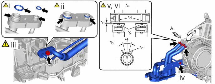
| *a | View A | *b | View B |
| *c | Positioning Rib | *d | Marking |
| *e | Hose Clip Installation Range (0 to 3 mm (0 to 0.118 in.)) | *f | Hose Clip Installation Angle (60°) |
Remove the vinyl tape from the No. 6 air conditioning tube and accessory assembly and then apply a sufficient amount of compressor oil to 2 new O-rings and the fitting surface of the rear cooling unit expansion valve and No. 6 air conditioning tube and accessory assembly.
- Compressor Oil:
-
ND-OIL 8 or equivalent
Install the 2 O-rings to the No. 6 air conditioning tube and accessory assembly.
- NOTICE:
-
Keep the O-rings and O-ring fitting surfaces free of foreign matter.
Install the No. 6 air conditioning tube and accessory assembly with the bolt.
- Torque:
- 5.4 N*m (55 kgf*cm, 48 in.*lbf)
- NOTICE:
-
Make sure not to cut the O-ring while installing it. (Cut O-rings cannot be installed.)
Install the screw.
Align the marking of the No. 6 air conditioning tube and accessory assembly with the positioning rib of the heater clamp and connect the No. 6 air conditioning tube and accessory assembly.
- NOTICE:
-
Do not apply excessive force to the No. 6 air conditioning tube and accessory assembly.
Install the 2 hose clips within the range shown in the illustration.
88561P 12.INSTALL REAR NO. 1 AIR CONDITIONING UNIT PACKING
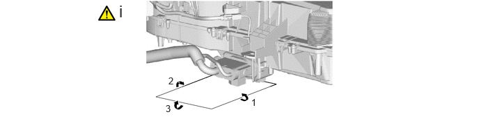
Apply the rear No. 1 air conditioning unit packing in the order shown in the illustration so that the piping section is not exposed.
- NOTICE:
-
Completely remove the remaining No. 1 air conditioning unit packing from the attachment surface during removal.
87103D 13.INSTALL REAR BLOWER MOTOR WITH FAN SUB-ASSEMBLY
87236C 14.INSTALL HEATER BLOWER COVER
87165C 15.INSTALL BLOWER MOTOR CONTROL
87217D 16.INSTALL REAR NO. 1 SIDE AIR DUCT

Install the rear No. 1 side air duct with the 2 screws in the order shown in the illustration.
87217E 17.INSTALL REAR NO. 2 SIDE AIR DUCT

Align the guide and install the rear No. 2 side air duct with the 3 screws in the order shown in the illustration.