LIGHTING (EXT) STOP LIGHT SWITCH INSTALLATION
CAUTION / NOTICE / HINT
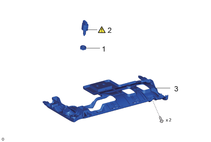
| Procedure | Part Name Code |

|

|

|
|
|---|---|---|---|---|---|
| 1 | STOP LIGHT SWITCH MOUNTING ADJUSTER | 84345 | - | - | - |
| 2 | STOP LIGHT SWITCH ASSEMBLY | 84340 | ( ) |
- | - |
| 3 | NO. 1 INSTRUMENT PANEL UNDER COVER SUB-ASSEMBLY | 55606 | - | - | - |
CAUTION / NOTICE / HINT
- HINT:
-
·
Use the same procedure for RHD and LHD vehicles.
·The procedure listed below is for LHD vehicles.
PROCEDURE

 84345 1.INSTALL STOP LIGHT SWITCH MOUNTING ADJUSTER
84340 2.INSTALL STOP LIGHT SWITCH ASSEMBLY
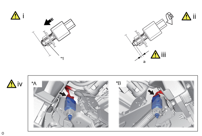
| *A | for LHD | *B | for RHD |
| *1 | Stop light switch mounting adjuster | - | - |

|
Install in this Direction | - | - |
Insert the stop light switch assembly to the stop light switch mounting adjuster until the switch body slightly touches the brake pedal.
- NOTICE:
-
·
When inserting the stop light switch assembly, make sure not to engage the brake pedal.
·Operate it while supporting it with one hand so that the brake pedal does not move.
Turn the stop light switch assembly 1/4 turn clockwise as shown in the illustration to install it.
- Torque:
- 1.5 N*m (15 kgf*cm, 13 in.*lbf)
-
or less
- NOTICE:
-
When inserting the stop light switch assembly, support the pedal from behind so that the pedal is not pushed in.
Check the protrusion of the plunger.
- Protrusion of the Plunger:
-
Area Measurement a 1.5 mm (0.0591 in.)
Connect the connector.
55606 3.INSTALL NO. 1 INSTRUMENT PANEL UNDER COVER SUB-ASSEMBLY