DOOR / HATCH POWER BACK DOOR SYSTEM B222049 Back Door Motor Internal Electronic Failure
DESCRIPTION
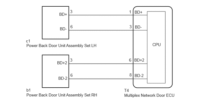
This DTC is stored when the multiplex network door ECU detects a malfunction of the motor built-into the power back door unit assembly set LH or power back door unit assembly set RH.
| DTC No. | Detection Item | DTC Detection Condition | Trouble Area | DTC Output from | Priority |
|---|---|---|---|---|---|
| B222049 | Back Door Motor Internal Electronic Failure | Malfunction of motor built into the power back door unit assembly set LH or power back door unit assembly set RH detected |
·
Multiplex network door ECU
·
Power back door unit assembly set LH
·
Power back door unit assembly set RH
·
Harness or connector |
Back Door | A |
WIRING DIAGRAM
CAUTION / NOTICE / HINT
- NOTICE:
-
If the multiplex network door ECU has been removed and installed or replaced, or if any of the connectors has been disconnected, initialize the power back door system.
-
Click hereVehicle Exterior>DOOR / HATCH>POWER BACK DOOR SYSTEM>INITIALIZATION
PROCEDURE
Clear the DTCs.
- Body Electrical > Back Door > Clear DTCs
- 50002 489
- Result:
-
Proceed to NEXT
NEXT
Turn the ignition switch to ON and wait for at least 10 seconds.
- Body Electrical > Back Door > Trouble Codes
- 50001 489
- Result:
-
Proceed to NEXT
NEXT
Check for DTCs.
- Body Electrical > Back Door > Trouble Codes
- 50001 489
- Result:
-
Result Proceed to B222049 is output A B222049 is not output B
A
B
Click hereGeneral>INTRODUCTION>HOW TO TROUBLESHOOT ECU CONTROLLED SYSTEMS>HOW TO PROCEED WITH TROUBLESHOOTING
Pre-procedure1
Fully open the back door.
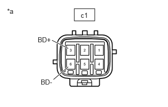
| *a | Component without harness connected (Power Back Door Unit Assembly Set LH) |
Disconnect the power back door unit assembly set LH connector.
Procedure1
Measure the resistance according to the value(s) in the table below.
- Standard Resistance:
-
Tester Connection Condition Specified Condition Click Location & Routing(c1)Location & Routingewd_type=routing;type=c;code=c1
Click Connector(c1)Body>No. 8 Floor Wire>Power Back Door Unit Assembly Set LHewd_type=component;type=c;code=c1;pinno=3,6
c1-3 (BD+) - Body ground Always 10 kΩ or higher c1-6 (BD-) - Body ground Always 10 kΩ or higher c1-3 (BD+) - c1-6 (BD-) Always Below 1 MΩ
- Result:
-
Proceed to OK NG
Post-procedure1
None
OK
NG
Pre-procedure1
Fully open the back door.
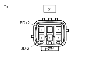
| *a | Component without harness connected (Power Back Door Unit Assembly Set RH) |
Disconnect the power back door unit assembly set RH connector.
Procedure1
Measure the resistance according to the value(s) in the table below.
- Standard Resistance:
-
Tester Connection Condition Specified Condition Click Location & Routing(b1)Location & Routingewd_type=routing;type=c;code=b1
Click Connector(b1)Body>No. 7 Floor Wire>Power Back Door Unit Assembly Set RHewd_type=component;type=c;code=b1;pinno=3,6
b1-3 (BD+2) - Body ground Always 10 kΩ or higher b1-6 (BD-2) - Body ground Always 10 kΩ or higher b1-3 (BD+2) - b1-6 (BD-2) Always Below 1 MΩ
- Result:
-
Proceed to OK NG
Post-procedure1
None
OK
NG
Pre-procedure1
Disconnect the T4 multiplex network door ECU connector.
Disconnect the c1 power back door unit assembly set LH connector.
Procedure1
Measure the resistance according to the value(s) in the table below.
- Standard Resistance:
-
Tester Connection Condition Specified Condition Click Location & Routing(T4,c1)Location & Routingewd_type=routing;type=c,c;code=T4,c1
Click Connector(T4)Body>No. 3 Floor Wire / Theft Warning Sensor Cord Sub-Assembly>Multiplex Network Door ECUewd_type=component;type=c;code=T4;pinno=1,3
Click Connector(c1)Body>No. 8 Floor Wire>Power Back Door Unit Assembly Set LHewd_type=component;type=c;code=c1;pinno=3,6
T4-1 (BD+) - c1-3 (BD+) Always Below 1 Ω T4-3 (BD-) - c1-6 (BD-) Always Below 1 Ω T4-1 (BD+) or c1-3 (BD+) - Body ground Always 10 kΩ or higher T4-3 (BD-) or c1-6 (BD-) - Body ground Always 10 kΩ or higher
- Result:
-
Proceed to OK NG
Post-procedure1
None
OK
NG
Pre-procedure1
Disconnect the T4 multiplex network door ECU connector.
Disconnect the b1 power back door unit assembly set RH connector.
Procedure1
Measure the resistance according to the value(s) in the table below.
- Standard Resistance:
-
Tester Connection Condition Specified Condition Click Location & Routing(T4,b1)Location & Routingewd_type=routing;type=c,c;code=T4,b1
Click Connector(T4)Body>No. 3 Floor Wire / Theft Warning Sensor Cord Sub-Assembly>Multiplex Network Door ECUewd_type=component;type=c;code=T4;pinno=6,8
Click Connector(b1)Body>No. 7 Floor Wire>Power Back Door Unit Assembly Set RHewd_type=component;type=c;code=b1;pinno=3,6
T4-6 (BD+2) - b1-3 (BD+2) Always Below 1 Ω T4-8 (BD-2) - b1-6 (BD-2) Always Below 1 Ω T4-6 (BD+2) or b1-3 (BD+2) - Body ground Always 10 kΩ or higher T4-8 (BD-2) or b1-6 (BD-2) - Body ground Always 10 kΩ or higher
- Result:
-
Proceed to OK NG
Post-procedure1
None
OK
NG