PARKING BRAKE ELECTRIC PARKING BRAKE SYSTEM Electric Parking Brake System AUTO Function Circuit
DESCRIPTION
The No. 2 skid control ECU (brake actuator assembly) receives shift position signals from the ECM*1, TCM*2 via CAN communication to control the electric parking brake system AUTO function (shift-linked).
The electric parking brake system AUTO function (shift-linked) is automatically disabled when the ignition switch is ON, the brake pedal is depressed and the shift lever is moved out of P. Then, if the shift lever is moved to P, the AUTO function (shift-linked) automatically operates to apply the electric parking brake.
*1: for 1GR-FE
*2: except 1GR-FE
WIRING DIAGRAM
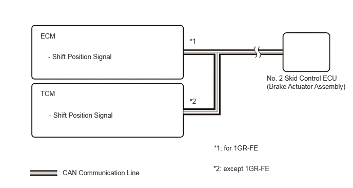
CAUTION / NOTICE / HINT
- NOTICE:
-
·
The AUTO function (shift-linked) will not be automatically disabled when the ignition switch is ON, the brake pedal is depressed and the shift lever is moved out from P if the electric parking brake switch assembly is moved to the engage side. The AUTO function (shift-linked) will not automatically operate to apply the electric parking brake when the shift lever is moved to P if the electric parking brake switch assembly is moved to the release side.
·To ensure that the electric parking brake does not operate, wait for 4 minutes or more with the ignition switch off, the driver door closed, and the brake pedal not depressed, then disconnect each connector, fuse and relay.
·After replacing the No. 2 skid control ECU (brake actuator assembly), perform "Calibration".
Click hereBrake>BRAKE CONTROL / DYNAMIC CONTROL SYSTEMS>ELECTRONICALLY CONTROLLED BRAKE SYSTEM>UTILITY
·When replacing the No. 2 skid control ECU (brake actuator assembly), operate the electric parking brake switch assembly as the parking brake indicator light blinks when the ignition switch is first turned ON.
PROCEDURE
Check the engine control specification.
- Result:
-
Result Proceed to 1GR-FE A except 1GR-FE B
A
B
Check for DTCs.
- Powertrain > Engine > Trouble Codes
- 50001 372
- Result:
-
Result Proceed to DTC is not output A DTC is output B
A
for LHD: Click hereBrake>BRAKE CONTROL / DYNAMIC CONTROL SYSTEMS>BRAKE ACTUATOR (for LHD)>REMOVAL
for RHD: Click hereBrake>BRAKE CONTROL / DYNAMIC CONTROL SYSTEMS>BRAKE ACTUATOR (for RHD)>REMOVAL
B
Click hereEngine / Hybrid System>1GR-FE (ENGINE CONTROL)>SFI SYSTEM>HOW TO PROCEED WITH TROUBLESHOOTING
Check for DTCs.
- Powertrain > Transmission > Trouble Codes
- 50001 373
- Result:
-
Result Proceed to DTC is not output A DTC is output B
A
for LHD: Click hereBrake>BRAKE CONTROL / DYNAMIC CONTROL SYSTEMS>BRAKE ACTUATOR (for LHD)>REMOVAL
for RHD: Click hereBrake>BRAKE CONTROL / DYNAMIC CONTROL SYSTEMS>BRAKE ACTUATOR (for RHD)>REMOVAL
B