POWER ASSIST SYSTEMS POWER STEERING SYSTEM(w/ Variable Flow Control Solenoid Valve) PRECAUTION
HANDLING PRECAUTION
When handling electronic parts:
Do not subject any parts such as ECUs and relays to any impact. Replace them with new ones if dropped or subjected to a strong impact.
Do not expose any electronic parts to high temperatures or humidity.
In order to prevent deformation or malfunctions due to static electricity, do not touch the connector terminals.
When handling the power steering ECU with motor assembly:
When replacing the power steering ECU with motor assembly, make sure to replace each power steering ECU with motor assembly with a new one.
- NOTICE:
-
·
Do not use a power steering ECU with motor assembly intended for another vehicle (demo models, etc.).
·When the power steering ECU with motor assembly has been replaced, perform ECU security key registration.
Click hereGeneral>SETUP>WHEN REPLACING OR REMOVING/INSTALLING PARTS>UPDATE ECU SECURITY KEY
When the power steering ECU with motor assembly has been replaced, perform Steering Actuator ECU Initial Setting (assist map writing).
When handling the steering system:
Care must be taken when replacing parts. Incorrect replacement could affect the performance of the steering system and result in driving hazards.
Complete the adjustment of the steering wheel and wheel alignment, and then initialize the steering sensor. If the order is reversed, the steering wheel and wheel alignment will become misaligned.
When handling the electric power steering column sub-assembly:
Do not subject the electric power steering column sub-assembly (especially the motor and torque sensor) to any impact. Replace the electric power steering column sub-assembly with a new one if subjected to a strong impact.
Do not pull the wire harness when moving the electric power steering column sub-assembly.
When the electric power steering column sub-assembly has been replaced, perform Steering Actuator ECU Initial Setting (assist map writing).
When disconnecting and reconnecting the connectors:
Before disconnecting connectors related to the power steering system, turn the ignition switch to ON, center the steering wheel, turn the ignition switch off, and then disconnect the connectors.
Before reconnecting connectors related to the power steering system, ensure that the ignition switch is off. Then center the steering wheel and turn the ignition switch to ON.
- NOTICE:
-
Do not turn the ignition switch to ON when the steering wheel is not centered.
If the above steps are not performed, the steering center point (zero point) may be offset causing a difference in steering effort when turning left and right. If there is a difference in steering effort when turning left and right, perform Steering Actuator ECU Initial Setting (assist map writing).
PRECAUTIONS FOR CAN COMMUNICATION
CAN communication lines are used to receive information from the No. 2 skid control ECU (brake actuator assembly) and ECM and to transmit warnings to the combination meter assembly. When problems are detected in the CAN communication lines, CAN communication DTCs are stored.
If any CAN communication system DTCs are output, perform troubleshooting for the CAN communication system first.
The wiring used for each communication line is a twisted pair of wires that have an equal length. Do not temporarily repair a CAN communication line with a bypass wire or equivalent.
HANDLING PRECAUTIONS FOR SRS AIRBAG SYSTEM
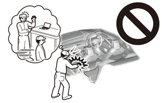
This vehicle is equipped with a Supplemental Restraint System (SRS). Failure to carry out service operations in the correct sequence could cause the SRS to unexpectedly deploy during servicing. This may cause a serious accident.
Before servicing (including inspection, replacement, removal and installation of parts), be sure to read the precautionary notices for the Supplemental Restraint System.
Click hereVehicle Interior>SUPPLEMENTAL RESTRAINT SYSTEMS>AIRBAG SYSTEM>PRECAUTION