STEERING GEAR / LINKAGE STEERING GEAR REASSEMBLY
CAUTION / NOTICE / HINT
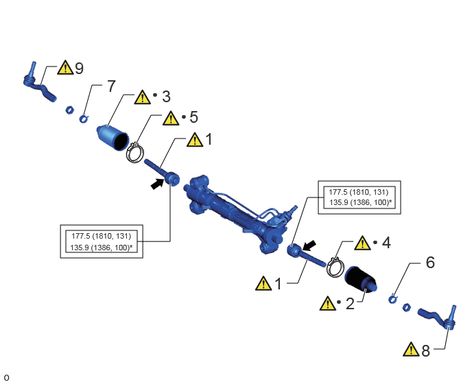
| Procedure | Part Name Code |

|

|

|
|
|---|---|---|---|---|---|
| 1 | STEERING RACK END SUB-ASSEMBLY | 45503 | ( ) |
- | - |
| 2 | NO. 1 STEERING RACK BOOT (for LH Side) | 45535 | () |
- | - |
| 3 | NO. 1 STEERING RACK BOOT (for RH Side) | 45535 | () |
- | - |
| 4 | NO. 2 STEERING RACK BOOT CLAMP | 45536A | () |
- | - |
| 5 | NO. 1 STEERING RACK BOOT CLAMP | 45535D | () |
- | - |
| 6 | STEERING RACK BOOT CLIP (for LH Side) | 45535B | - | - | - |
| 7 | STEERING RACK BOOT CLIP (for RH Side) | 45535B | - | - | - |
| 8 | TIE ROD END SUB-ASSEMBLY LH | 45047 | () |
- | - |
| 9 | TIE ROD END SUB-ASSEMBLY RH | 45046 | () |
- | - |

|
Tightening torque for "Major areas involving basic vehicle performance such as moving/turning/stopping": N*m (kgf*cm, ft.*lbf) | * | For use with SST |
| ● | Non-reusable part |

|
MP Grease |
CAUTION / NOTICE / HINT
- HINT:
-
·
Use the same procedure for RHD and LHD vehicles.
·The procedure listed below is for LHD vehicles.
PROCEDURE

 45503 1.INSTALL STEERING RACK END SUB-ASSEMBLY
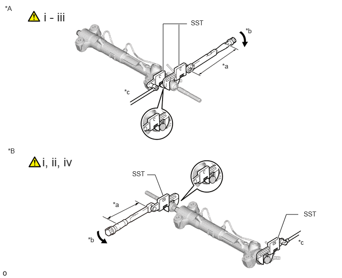
| *A | for LH Side | *B | for RH Side |
| *a | Torque Wrench Fulcrum Length | *b | Turn |
| *c | Hold | - | - |
Temporarily install the 2 steering rack end sub-assemblies to the power steering rack sub-assembly.
Fill up the ball joint of the 2 steering rack end sub-assemblies with MP grease.
for LH side:
Using SST, tighten the steering rack end sub-assembly to the power steering rack sub-assembly.
- SST
-
09922-10010
- Torque:
- Specified tightening torque : 177.5 N*m (1810 kgf*cm, 131 ft.*lbf)
- HINT:
-
·
Calculate the torque wrench reading when changing the fulcrum length of the torque wrench.
Click hereGeneral>INTRODUCTION>REPAIR INSTRUCTION>PRECAUTION
·When using SST (fulcrum length of 122.5 mm (4.823 in.)) + torque wrench (fulcrum length of 400 mm (15.748 in.)): 135.9 N*m (1386 kgf*cm, 100 ft.*lbf)
·Rotate SST in the direction shown in the illustration.
for RH Side:
Using SST, tighten the steering rack end sub-assembly to the power steering rack sub-assembly.
- SST
-
09922-10010
- Torque:
- Specified tightening torque : 177.5 N*m (1810 kgf*cm, 131 ft.*lbf)
- HINT:
-
·
Calculate the torque wrench reading when changing the fulcrum length of the torque wrench.
Click hereGeneral>INTRODUCTION>REPAIR INSTRUCTION>PRECAUTION
·When using SST (fulcrum length of 122.5 mm (4.823 in.)) + torque wrench (fulcrum length of 400 mm (15.748 in.)): 135.9 N*m (1386 kgf*cm, 100 ft.*lbf)
·Rotate SST in the direction shown in the illustration.
45535 2.INSTALL NO. 1 STEERING RACK BOOT (for LH Side)
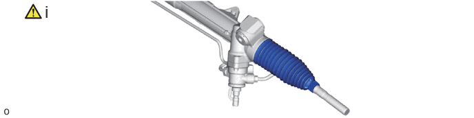
Install the No. 1 steering rack boot to the groove on the rack housing.
- NOTICE:
-
·
Be careful not to damage or twist the No. 1 steering rack boot.
·Make sure that the No. 1 steering rack boot is free of rust and foreign matter.
·Make sure that the boot is free of water, rust, foreign matter, etc.
·Do not touch the inside of the rack boot or rack bar when performing installation.
45535 3.INSTALL NO. 1 STEERING RACK BOOT (for RH Side)
Perform the same procedure as for the LH side.
45536A 4.INSTALL NO. 2 STEERING RACK BOOT CLAMP
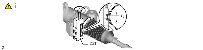
| *a | 3.0 mm (0.118 in.) or less | - | - |
Using SST, install a new No. 2 steering rack boot clamp as shown in the illustration.
- SST
-
09521-24010
- NOTICE:
-
·
Do not excessively crimp the No.2 steering rack boot clamp.
·Make sure that the No. 1 steering rack boot is not twisted.
·Be careful not to damage the No. 1 steering rack boot.
45535D 5.INSTALL NO. 1 STEERING RACK BOOT CLAMP
Use the same procedure described for the No. 2 steering rack boot clamp.
45535B 6.INSTALL STEERING RACK BOOT CLIP (for LH Side)
45535B 7.INSTALL STEERING RACK BOOT CLIP (for RH Side)
45047 8.INSTALL TIE ROD END SUB-ASSEMBLY LH
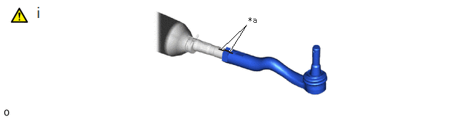
| *a | Matchmark | - | - |
Install the nut and tie rod end sub-assembly LH to the steering rack end sub-assembly until the matchmarks are aligned.
- HINT:
-
After adjusting toe-in, tighten the nut.
45046 9.INSTALL TIE ROD END SUB-ASSEMBLY RH
Perform the same procedure as for the LH side.