V35A-FTS ENGINE CONTROL SFI SYSTEM Turbocharger Oil Leak and White Smoke
DESCRIPTION
| Type of Oil Leak | Outline | Major Trouble Area |
|---|---|---|
| Internal oil leak (white smoke) | Oil leak from the bearing housing into the compressor housing (intake side) or turbine housing (exhaust side) through the seal ring. Internal oil leaks cannot be seen from outside the turbocharger. If an oil leak occurs from the turbine seal, a large amount of white smoke is emitted from the exhaust pipe. |
·
Compressor seal ring
·
Turbine seal ring
·
Oil drain blockage
·
Damaged shaft
·
Shaft or bearing seized
·
Damaged compressor impeller
·
Low-quality fuel |
| External oil leak | Oil leak from inside to outside the turbocharger. (Example: FIPG seal, oil pipe flange, or oil pipe union) Includes oil leaks that are visible outside the turbocharger. |
·
FIPG seal
·
Oil pipe flange
·
Oil pipe union
·
Intake pipe hose connector
·
Compressor housing flange connector |
- HINT:
-
·
Turbocharger oil leaks are classified into two types, internal oil leaks and external oil leaks.
·The following illustration shows the parts of the turbocharger.
·If an oil leak or white smoke occurs, sometimes the turbocharger is replaced even though it is not the cause of the problem.
·Oil may leak from the seal ring if the turbocharger is placed with its shaft vertical. However, this is unrelated to oil leaks during operation.
·Oil traces on the compressor housing surface or oil at the compressor inlet or outlet can mistakenly be evaluated as a leak from the turbocharger.
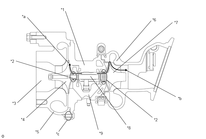
| *1 | Bearing Housing | *2 | Seal Ring |
| *3 | Compressor Inlet | *4 | Compressor Impeller |
| *5 | Compressor Housing | *6 | Turbine Housing |
| *7 | Turbine Wheel | *8 | Turbine Shaft |
| *9 | Oil Drain | - | - |
| *a | Internal oil leak to compressor housing | *b | Internal oil leak to turbine housing |
| *c | FIPG Sealing Part | - | - |
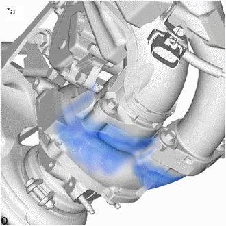
| *a | Fig. 1 |
- HINT:
-
Oil staining, as shown in Illustration 1, may result from oil sprayed from turbocharger peripheral parts or oil leaks from the air cleaner hose. Oil staining on the outer surface of the turbocharger does not indicate an oil leak from the turbocharger. It is also unrelated to white smoke. To identify actual turbocharger external oil leaks, check only the seal areas shown in Illustrations 2 and 3.
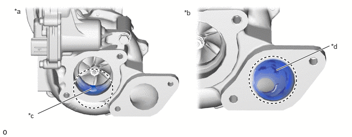
| *a | Fig. 2 | *b | Fig. 3 |
| *c | Oil Existence at Compressor Inlet (Max. 5 cm3) | *d | Oil Existence at Compressor Outlet |
- HINT:
-
·
As the blowby gas containing oil mist is returned to the intake system by the PCV, a certain amount of oil enters the intake system. The amount of oil at the compressor inlet shown in Illustration 2 is the normal amount and does not indicate an oil leak (internal oil leak) from the turbocharger. The amount of oil shown at the compressor outlet in Illustration 3 is also the normal amount.
·The surface of the compressor impeller may be blackened by the blowby gas. This does not indicate a malfunction.
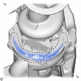
| *a | Fig. 4 |
| *b | In an actual oil leak, oil leaks from the FIPG seal. |
- HINT:
-
Illustration 4 shows how to check for air leaks from the position of an oil leak using soapy water. Bubbles form where the leak is occurring.
Faults and Symptoms of Turbocharger Parts
| Main fault | Seal ring damage |
| Symptom |
·
Oil leak into compressor housing
·
Excessive oil consumption |
| Note |
·
If the compressor seal ring is defective, a large oil leak may be found between the compressor outlet and the intercooler and between the intercooler and intake manifold.
·
If a large oil leak is found in the compressor inlet, the oil did not come from the turbocharger. It may indicate a malfunction in the PCV system. |
| Main fault | Seal ring damage |
| Symptom |
·
Oil leak into turbine housing
·
Large amount of white smoke emitted from the exhaust pipe
·
Excessive oil consumption |
| Note |
·
If the turbine seal ring is defective, a large amount of white smoke is emitted continuously.
·
If the white smoke is emitted only immediately after the engine is started and then disappears, or if a small amount of smoke is emitted intermittently, the oil did not come from the turbocharger. Another part may be defective.
·
If wet oil is found at the turbine inlet, the oil did not come from the turbocharger. Another part may be defective. |
| Main fault | Blocked oil drain due to oil coking |
| Symptom | Large amount of white smoke emitted from the exhaust pipe |
- HINT:
-
·
Oil coking results due to inadequate oil management
·If the oil drain is blocked due to oil coking, the oil cannot be removed smoothly. Oil leaking from the bearing housing into the compressor housing and turbine housing generates a large amount of white smoke in the exhaust pipe.
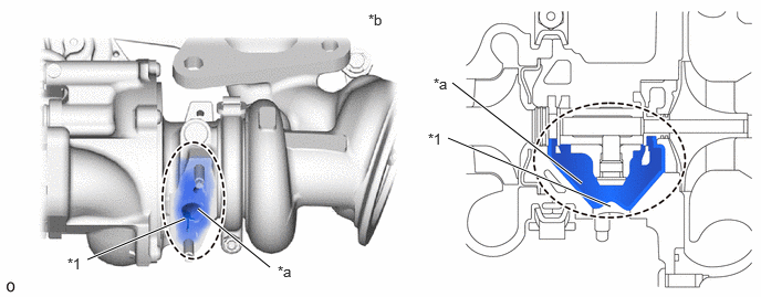
| *1 | Oil Drain | - | - |
| *a | Coked Oil | *b | Oil Drain Clogged with Coked Oil |
| Main fault |
·
Damage
·
Seized |
| Symptom |
·
Shaft does not rotate
·
Oil leak into compressor housing
·
Large amount of white smoke emitted from the exhaust pipe
·
Lack of power
·
Abnormal noise from the turbocharger |
| Note |
·
A turbine shaft defect may cause a sensation of a lack of power due to inadequate boost pressure.
·
At low temperatures, shaft rotation may feel heavy due to the oil viscosity. Do not mistake this for non-rotating shaft. |
| Main fault | Damage |
| Symptom |
·
Shaft does not rotate
·
Oil leak into compressor housing
·
Lack of power |
| Note |
·
If the compressor impeller is defective, a large oil leak may be found between the compressor outlet and the intercooler and between the intercooler and intake manifold.
·
The boost pressure may stop the oil at the compressor seal ring. If the boost pressure does not rise due to a damaged compressor impeller, oil flows into the compressor housing. |
| Main fault | Oil leak from the FIPG seal |
| Symptom |
·
If an oil stain is separate from the FIPG seal, it may be evaluated as oil sprayed from turbocharger peripheral parts.
·
If the oil stain reaches the flange connector, it may be evaluated as a defective flange connection. |
| Main fault | Oil leak from the compressor inlet elbow and intake hose connector. |
| Symptom | If oil stain traces exist at the hose or flange connector, it may be evaluated as a defective hose or flange connection. |
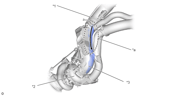
| *1 | Air Inlet Duct | *2 | Compressor Housing |
| *3 | Compressor Inlet Elbow | - | - |
| *a | Oil Leak from Hose Connection Part | - | - |
PROCEDURE
Check whether the oil leak is internal or external.
- HINT:
-
White smoke is unrelated to external oil leaks.
-
Type of Oil Leak Outline Internal oil leak (white smoke) An internal oil leak from the bearing housing into the compressor housing (intake side) or turbine housing (exhaust side) through the seal ring cannot be seen from outside the turbocharger. If an oil leak occurs from the turbine seal, a large amount of white smoke is emitted from the exhaust pipe. External oil leak Oil leak from inside to outside the turbocharger. (Example: FIPG seal, oil pipe flange, or oil pipe union) Includes oil leaks that are visible outside the turbocharger.
- Result:
-
Result Proceed to External oil leak (Oil leak from the contact surface between the compressor housing and the seal plate or between the seal plate and the bearing housing) A External oil leak (Oil leak from the contact surface between the compressor inlet elbow or the compressor outlet elbow and the compressor housing) B Internal oil leak C
- HINT:
-
Perform "Inspection After Repair" after replacing the turbocharger sub-assembly.
-
Click hereEngine / Hybrid System>V35A-FTS (ENGINE CONTROL)>SFI SYSTEM>INITIALIZATION
A
B
C
Repair or replace the parts that are leaking oil.
- HINT:
-
·
If oil leaks from the contact surface between the compressor inlet elbow and the compressor housing, the installation may be incorrect due to loose nuts or a defective gasket. Check the installation or replace the gasket.
·If oil leaks from the contact surface between the compressor outlet elbow and the compressor housing, the installation may be incorrect due to loose nuts or a defective gasket. Check the installation or replace the gasket.
- Result:
-
Proceed to NEXT
NEXT
Remove the compressor inlet elbow from the turbocharger sub-assembly.
Check for excessive oil or oil deposits at the compressor inlet.
- HINT:
-
·
The PCV gas contains a certain amount of oil mist. This can accumulate in front of the compressor inlet, creating a certain amount of oil, as shown in Illustration 2.
·Excessive oil at the compressor inlet may cause a malfunction in the PCV system.
·A certain amount of oil on the compressor housing surface results from oil mist in the blowby gas and is not a malfunction.
Remove the compressor outlet elbow from the turbocharger sub-assembly.
Check for excessive oil or oil deposits at the compressor outlet.
- HINT:
-
The PCV gas contains a certain amount of oil mist. This can create a certain amount of oil, as shown in Illustration 3.
Remove the converter assembly.
Check for excessive oil or oil deposits in the turbine housing.
- HINT:
-
·
Do not mistake carbon soot for oil.
·If the turbocharger shaft is tilted, a small amount of oil flows out of the bearing housing. Do not mistake oil that flows out of the bearing housing during and after removal of the turbocharger sub-assembly for oil that existed before the turbocharger assembly was removed.
·Excessive oil or oil deposits in the turbine inlet comes from a cylinder exhaust port and may indicate a problem with one or more cylinders.
- Result:
-
Result Proceed to No excessive oil in the compressor inlet or outlet or the turbine housing A Excessive oil in the compressor inlet or outlet B Excessive oil in the turbine housing C
A
B
C
Check for damage to the compressor impeller.
Check for interference between the compressor impeller and the compressor housing.
- Result:
-
Result Proceed to No damage or interference A Damage or interference exists B
A
B
Check that the turbine shaft rotates smoothly, without catching.
Click hereEngine / Hybrid System>V35A-FTS (INTAKE / EXHAUST)>TURBOCHARGER>INSPECTION
Check for loose turbine mounting nuts and for axial play in the turbine shaft.
Click hereEngine / Hybrid System>V35A-FTS (INTAKE / EXHAUST)>TURBOCHARGER>INSPECTION
- HINT:
-
If the turbine shaft catches or if there is no play or excessive play, it could indicate a seal problem due to seizing or poor sliding due to a deposit build up.
- Standard value:
-
0.10 mm (0.00394 in.) or less
- Result:
-
Result Proceed to No turbine shaft malfunction A Turbine shaft malfunction B
- HINT:
-
Perform "Inspection After Repair" after replacing the turbocharger sub-assembly.
-
Click hereEngine / Hybrid System>V35A-FTS (ENGINE CONTROL)>SFI SYSTEM>INITIALIZATION
A
B
Remove the turbo oil inlet pipe sub-assembly.
Check for blockage of the turbo oil inlet pipe sub-assembly due to accumulated deposits or deformation.
- HINT:
-
If no malfunction exists in the turbo oil inlet pipe sub-assembly, there may be a seal defect due to oil coking in the bearing housing.
- Result:
-
Result Proceed to No clogging A Clogging B
- HINT:
-
Perform "Inspection After Repair" after replacing the turbocharger sub-assembly.
-
Click hereEngine / Hybrid System>V35A-FTS (ENGINE CONTROL)>SFI SYSTEM>INITIALIZATION
A
B
Check for interference between the turbine wheel and the turbine housing.
- Result:
-
Result Proceed to No damage or interference A Damage or interference exists B
- HINT:
-
Perform "Inspection After Repair" after replacing the turbocharger sub-assembly.
-
Click hereEngine / Hybrid System>V35A-FTS (ENGINE CONTROL)>SFI SYSTEM>INITIALIZATION
A
B
Check for damage to the turbine wheel.
Check for interference between the turbine wheel and the turbine housing.
- Result:
-
Result Proceed to The turbine wheel is not damaged and there is no interference between the turbine wheel and turbine housing A Turbine wheel is damaged
(there is no interference between the turbine wheel and turbine housing)B There is interference between the turbine wheel and turbine housing
- HINT:
-
Perform "Inspection After Repair" after replacing the turbocharger sub-assembly.
-
Click hereEngine / Hybrid System>V35A-FTS (ENGINE CONTROL)>SFI SYSTEM>INITIALIZATION
A
B