V35A-FTS ENGINE CONTROL SFI SYSTEM Lack of Power (Turbocharger System)
CAUTION / NOTICE / HINT
- HINT:
-
·
The diagnosis flowchart is for lack of power due to turbocharger factors.
·If symptom-specific diagnosis indicates a turbocharger related problem, check using this flowchart.
PROCEDURE
Start the engine and warm it up until the engine coolant temperature reaches 75°C (167°F) or higher.
Turn the ignition switch off and wait for at least 30 seconds.
Start the engine and wait 1 minute or more.
Read the DTCs.
- Powertrain > Engine > Trouble Codes
- 50001 372
- Result:
-
Result Proceed to DTCs are not output A DTC is output B
A
B
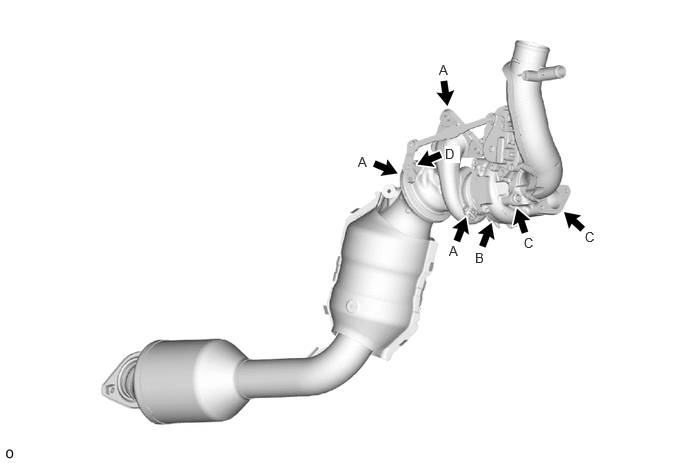
Check that no soot or oil adheres to the turbocharger sub-assembly connectors.
- HINT:
-
If adhering soot or an oil leak exists, air leaking at that position may be the cause of the lack of boost pressure.
- Result:
-
Result Proceed to No adhering soot or an oil A Soot adhering around the turbine housing, flange, or V band (A in the illustration) B Oil leak from the contact surface between the compressor housing and the seal plate or between the seal plate and the bearing housing (B in the illustration) Oil leak from the compressor housing flange (C in the illustration) Soot adhering around the bushing (D in the illustration) C
- HINT:
-
Perform "Inspection After Repair" after replacing the turbocharger sub-assembly.
-
Click hereEngine / Hybrid System>V35A-FTS (ENGINE CONTROL)>SFI SYSTEM>INITIALIZATION
A
B
C
Check that the turbine shaft rotates smoothly, without catching.
Click hereEngine / Hybrid System>V35A-FTS (INTAKE / EXHAUST)>TURBOCHARGER>INSPECTION
- HINT:
-
If the turbine shaft catches, it could indicate poor sliding due to seal damage due to seizing or a deposit build-up.
- Result:
-
Result Proceed to No turbine shaft malfunction A Turbine shaft malfunction B
A
B
Check for damage to the turbine wheel.
Check for interference between the turbine wheel and the turbine housing.
- Result:
-
Result Proceed to No damage or interference A Damage or interference exists B
- HINT:
-
Perform "Inspection After Repair" after replacing the turbocharger sub-assembly.
-
Click hereEngine / Hybrid System>V35A-FTS (ENGINE CONTROL)>SFI SYSTEM>INITIALIZATION
A
B
Check for loose turbine mounting nuts and for axial play in the turbine shaft.
Click hereEngine / Hybrid System>V35A-FTS (INTAKE / EXHAUST)>TURBOCHARGER>INSPECTION
- HINT:
-
If there is no play or excessive play, it could indicate poor sliding due to seal damage due to seizing or a deposit build-up.
- Standard value:
-
0.10 mm (0.00394 in.) or less
- HINT:
-
·
If there no play or excessive play, it could indicate poor sliding due to seal damage due to seizing or a deposit build-up.
·If there is no malfunction in the turbine shaft, the waste gate valve actuator, waste gate valve or turbine housing may be malfunctioning.
- Result:
-
Result Proceed to No turbine shaft malfunction A Turbine shaft malfunction B
- HINT:
-
Perform "Inspection After Repair" after replacing the turbocharger sub-assembly.
-
Click hereEngine / Hybrid System>V35A-FTS (ENGINE CONTROL)>SFI SYSTEM>INITIALIZATION
A
B
Check for interference between the turbine wheel and the turbine housing.
- Result:
-
Result Proceed to No damage or interference A Damage or interference exists B
- HINT:
-
Perform "Inspection After Repair" after replacing the turbocharger sub-assembly.
-
Click hereEngine / Hybrid System>V35A-FTS (ENGINE CONTROL)>SFI SYSTEM>INITIALIZATION
A
B
Check that the bushing of the turbine housing waste gate valve link is free of cracks and the play does not exceed 0.5 mm.
- Standard:
-
No cracks and play does not exceed 0.5 mm (0.0196 in.)
- Result:
-
Proceed to OK NG
- HINT:
-
Perform "Inspection After Repair" after replacing the turbocharger sub-assembly.
-
Click hereEngine / Hybrid System>V35A-FTS (ENGINE CONTROL)>SFI SYSTEM>INITIALIZATION
OK
NG