PARK ASSIST / MONITORING TOYOTA PARKING ASSIST-SENSOR SYSTEM No. 1 Clearance Warning Buzzer Circuit
DESCRIPTION
This circuit consists of the No. 1 clearance warning buzzer and clearance warning ECU assembly. An ECU-excited type buzzer is used. The ECU operates the buzzers using a sound pattern that changes depending on the distance to the obstacle.
WIRING DIAGRAM
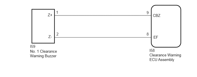
PROCEDURE
Check that the buzzer operates by performing the Active Test.
- Body Electrical > Clearance Warning > Active Test
-
Tester Display Measurement Item Control Range Diagnostic Note Front Buzzer No. 1 clearance warning buzzer OFF or ON Confirm that the vehicle is stopped and the ignition switch is ON
- Body Electrical > Clearance Warning > Active Test
-
Tester Display Front Buzzer - 50004 438 1
- OK:
-
The No. 1 clearance warning buzzer sounds.
- Result:
-
Proceed to OK NG
OK
NG
Disconnect the I58 clearance warning ECU assembly connector.
Disconnect the I59 No. 1 clearance warning buzzer connector.
Measure the resistance according to the value(s) in the table below.
- Standard Resistance:
-
Tester Connection Condition Specified Condition Click Location & Routing(I58,I59)Location & Routingewd_type=routing;type=c,c;code=I58,I59
I58-9 (CBZ) - I59-1 (Z+) Always Below 1 Ω I58-8 (EF) - I59-2 (Z-) Always Below 1 Ω I58-9 (CBZ) or I59-1 (Z+) - Body ground Always 10 kΩ or higher I58-8 (EF) or I59-2 (Z-) - Body ground Always 10 kΩ or higher
- Result:
-
Proceed to OK NG
OK
NG
Replace the No. 1 clearance warning buzzer with a new or known good one.
Click hereAudio / Visual / Telematics>PARK ASSIST / MONITORING>CLEARANCE WARNING BUZZER (for Rear)>REMOVAL
- Result:
-
Proceed to NEXT
NEXT
Check that the buzzer operates by performing the Active Test.
- Body Electrical > Clearance Warning > Active Test
-
Tester Display Measurement Item Control Range Diagnostic Note Front Buzzer No. 1 clearance warning buzzer OFF or ON Confirm that the vehicle is stopped and the ignition switch is ON
- Body Electrical > Clearance Warning > Active Test
-
Tester Display Front Buzzer - 50004 438 1
- OK:
-
The No. 1 clearance warning buzzer sounds.
- Result:
-
Proceed to OK NG
OK
NG