HEATING / AIR CONDITIONING AIR CONDITIONING SYSTEM B144088 Rear Servo Motor LIN Communication Bus off
DESCRIPTION
The No. 1 cooler wiring harness sub-assembly connects the air conditioning amplifier assembly and the servo motors. The air conditioning amplifier assembly supplies power and sends operation instructions to each servo motor through the No. 2 air conditioning harness assembly. Each servo motor sends damper position information to the air conditioning amplifier assembly.
| DTC No. | Detection Item | DTC Detection Condition | Trouble Area | Memory | DTC Output from | Priority |
|---|---|---|---|---|---|---|
| B144088 | Rear Servo Motor LIN Communication Bus off | Diagnosis Condition: Ignition switch ON Malfunction Status: Error or lost communication with each servo motor Detection Time: Continuously for 10 seconds or more |
·
No. 1 cooler wiring harness sub-assembly
·
Rear air mix damper servo sub-assembly
·
No. 2 rear air mix damper servo sub-assembly
·
Rear mode damper servo sub-assembly
·
Air conditioning amplifier assembly |
Memorized | Air Conditioner | A |
| Vehicle Condition | |||
|---|---|---|---|
| Pattern 1 | Pattern 2 | ||
| Diagnosis Condition | Ignition switch ON | ○ | ○ |
| Malfunction Status | Error communication with each servo motor | ○ | - |
| Lost communication with each servo motor | - | ○ | |
| Detection Time | Continuously for 10 seconds or more | Continuously for 10 seconds or more | |
| Trip Count | 1 trip | 1 trip | |
- HINT:
-
If the conditions of either of these patterns are detected, a DTC will be stored.
WIRING DIAGRAM
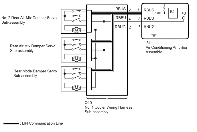
CAUTION / NOTICE / HINT
- NOTICE:
-
·
This DTC is also output for the damper link, damper lock, etc. Before performing inspection, perform servomotor initialization and check that there are no mechanical malfunctions.
Click hereVehicle Interior>HEATING / AIR CONDITIONING>AIR CONDITIONING SYSTEM>INITIALIZATION
·This DTC is also output when servomotor initialization has failed. When servomotor initialization has failed, repair any malfunctions and perform servomotor initialization again.
Click hereVehicle Interior>HEATING / AIR CONDITIONING>AIR CONDITIONING SYSTEM>INITIALIZATION
PROCEDURE
Perform the Active Test according to the display on the GTS.
- Body Electrical > Air Conditioner > Active Test
-
Tester Display Measurement Item Control Range Diagnostic Note Rear Left Air Mix Damper Control Servo Motor Rear air mix damper servo sub-assembly operation Min.: 128
Max.: 384Operates between 254 to 299 pulses Rear Right Air Mix Damper Control Servo Motor No. 2 rear air mix damper servo sub-assembly operation Min.: 128
Max.: 384Operates between 213 to 258 pulses Rear Air Outlet Damper Control Servo Motor Rear mode damper servo sub-assembly operation Min.: 128
Max.: 384Operates between 200 to 276 pulses
- Body Electrical > Air Conditioner > Active Test
-
Tester Display Rear Left Air Mix Damper Control Servo Motor - 50004 450 42
- Body Electrical > Air Conditioner > Active Test
-
Tester Display Rear Right Air Mix Damper Control Servo Motor - 50004 450 43
- Body Electrical > Air Conditioner > Active Test
-
Tester Display Rear Air Outlet Damper Control Servo Motor - 50004 450 51
- Result:
-
Result Proceed to All of the damper servo motors do not operate A Any of the damper servo motors does not operate B All of the damper servo motors operate C
A
B
C
Pre-procedure1
Disconnect the I31 air conditioning amplifier assembly connector.
Disconnect the Q10 No. 1 cooler wiring harness sub-assembly connector.
Procedure1
Measure the resistance according to the value(s) in the table below.
- Standard Resistance:
-
Tester Connection Condition Specified Condition Click Location & Routing(I31,Q10)Location & Routingewd_type=routing;type=c,c;code=I31,Q10
I31-7 (RBUS) - Q10-3 (RBUS) Always Below 1 Ω I31-2 (RBBU) - Q10-4 (RBBU) Always Below 1 Ω I31-3 (RBUG) - Q10-2 (RBUG) Always Below 1 Ω I31-7 (RBUS) or Q10-3 (RBUS) - Other terminals and body ground Always 10 kΩ or higher I31-2 (RBBU) or Q10-4 (RBBU) - Other terminals and body ground Always 10 kΩ or higher I31-3 (RBUG) or Q10-2 (RBUG) - Other terminals and body ground Always 10 kΩ or higher
- Result:
-
Proceed to OK NG
Post-procedure1
None
OK
NG
- NOTICE:
-
When inspecting the air conditioning amplifier assembly, do not bring the tester probes too close to each other as a short circuit may occur.
Pre-procedure1
Disconnect the I31 air conditioning amplifier assembly connector.
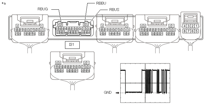
| *a | Component without harness connected (Air Conditioning Amplifier Assembly) |
- | - |
Procedure1
Measure the resistance according to the value(s) in the table below.
- Standard Resistance:
-
Tester Connection Condition Specified Condition 3 (RBUG) - Body ground Always Below 1 Ω
Measure the voltage according to the value(s) in the table below.
- Standard Voltage:
-
Tester Connection Condition Specified Condition 2 (RBBU) - Body ground Always 11 to 14 V
Using an oscilloscope, check the waveform.
| Tester Connection | Tool Setting | Switch Condition |
|---|---|---|
| 7 (RBUS) - 3 (RBUG) | 2 V/DIV., 2 ms./DIV. | Ignition switch ON |
- OK:
-
Waveform is similar to that shown in the illustration.
- Result:
-
Proceed to OK NG
Post-procedure1
None
OK
NG