Home › Engine / Hybrid System › V35A-FTS (INTAKE / EXHAUST) › INTAKE AIR CONTROL VALVE
RM38G0E _51 Engine / Hybrid System _101528 V35A-FTS INTAKE / EXHAUST _0470491 INTAKE AIR CONTROL VALVE A

V35A-FTS INTAKE / EXHAUST  INTAKE AIR CONTROL VALVE  INSTALLATION  


CAUTION / NOTICE / HINT
COMPONENTS (INSTALLATION)
A483549N01
0.052,4.281 1.073,4.479 1.021,0.198 0.688,2.156 1.333,2.354 0.646,0.198 4.479,3.927 5.5,4.125 1.021,0.198 5.406,2.25 6.427,2.448 1.021,0.198 3.469,1.813 4.49,2.01 1.021,0.198 2.906,4.323 3.406,4.323 false 4,0.479 4.146,0.479 4.146,0.479 4.365,0.688 false 1.396,0.885 1.542,0.885 1.542,0.885 1.865,1.26 false 5.438,3.448 5.865,3.719 5.865,3.719 6.031,3.719 false 1.104,3.875 1.479,3.875 false 1.333,2.25 1.708,2.25 false 4.104,4.021 4.479,4.021 false 0.552,3.594 0.552,4.281 false 4.906,2.344 5.406,2.344 false 3.615,1.302 3.927,1.302 3.927,1.302 3.927,1.813 false 0.615,2.594 0.76,2.594 0.76,2.594 1.292,2.781 false 1.802,3.729 2.458,4.135 0.656,0.406 18 false 1 2.677,4.177 2.979,4.531 0.302,0.354 18 false 1 1.146,0.74 1.448,1.094 0.302,0.354 18 false 3 6.385,3.604 6.688,3.958 0.302,0.354 18 false 2 4.021,4.073 4.479,4.271 0.458,0.198 10 false x 3 0.708,3.49 1.167,3.688 0.458,0.198 10 false x 3 3.792,0.365 4.094,0.719 0.302,0.354 18 false 4 0.125,4.313 1.198,4.542 1.073,0.229 8 false 8.5 (87, 75 in.*lbf) 4.531,3.958 5.604,4.188 1.073,0.229 8 false 8.5 (87, 75 in.*lbf) 0.74,2.188 1.51,2.417 0.771,0.229 8 false 10 (102, 7) 1.854,2.281 2.313,2.479 0.458,0.198 10 false x 3 3.542,1.844 4.615,2.073 1.073,0.229 8 false 4.0 (41, 35 in.*lbf) 5.469,2.271 6.542,2.5 1.073,0.229 8 false 4.0 (41, 35 in.*lbf) 0.417,2.51 0.729,2.708 0.313,0.198 10 false *1

Procedure Part Name Code
Z101186

Z101188

Z101187

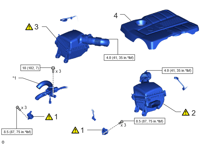
1 AIR BY-PASS VALVE ASSEMBLY 17670B (Click here) - -
2 AIR CLEANER ASSEMBLY LH WITH AIR CLEANER HOSE ASSEMBLY LH 17800 (Click here) - -
3 AIR CLEANER ASSEMBLY RH WITH AIR CLEANER HOSE ASSEMBLY RH 17700L (Click here) - -
4 V-BANK COVER SUB-ASSEMBLY 11209 - - -

*1 WIRE HARNESS - -
V100146

N*m (kgf*cm, ft.*lbf): Specified torque - -

CAUTION / NOTICE / HINT

PROCEDURE

Hide 17670B 1.INSTALL AIR BY-PASS VALVE ASSEMBLY

a.

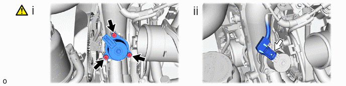
for Bank 2:

A483561N01
0.656,0.063 0.938,0.417 0.281,0.354 18 false i 4,0.073 4.281,0.427 0.281,0.354 18 false ii

i.

Using a T30 "TORX" socket wrench, install the air by-pass valve assembly with the 3 bolts.

Torque:
8.5 N*m (87 kgf*cm, 75 in.*lbf)


ii.

Connect the connector.


b.

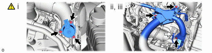
for Bank 1:

A483562N01
0.583,0.063 0.865,0.417 0.281,0.354 18 false i 3.729,0.073 4.219,0.406 0.49,0.333 18 true ii, iii

i.

Using a T30 "TORX" socket wrench, install the air by-pass valve assembly with the 3 bolts.

Torque:
8.5 N*m (87 kgf*cm, 75 in.*lbf)


ii.

Connect the wire harness with the 3 bolts.

Torque:
10 N*m (102 kgf*cm, 7 ft.*lbf)


iii.

Connect the 3 connectors.


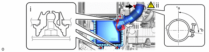
Hide 17800 2.INSTALL AIR CLEANER ASSEMBLY LH WITH AIR CLEANER HOSE ASSEMBLY LH

a.
A483536C01
1.583,1.021 1.76,1.188 0.177,0.167 10 true *b 3.323,0.052 3.521,0.313 0.198,0.26 18 true iii 0.948,0.219 1.26,0.375 0.313,0.156 10 false *a 2.281,0.083 2.448,0.344 0.167,0.26 18 true ii 5.479,0.177 5.615,0.427 0.135,0.25 18 true i
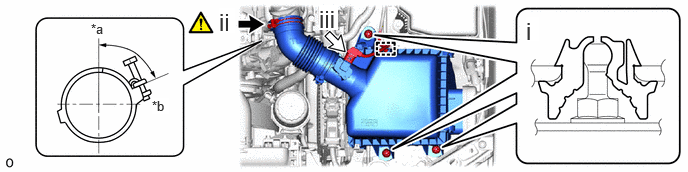
*a Upper Side *b RH Side


i.

Attach the 3 grommets to install the air cleaner assembly LH with air cleaner hose assembly LH.


ii.

Tighten the hose clamp in the position shown in the illustration.

Torque:
4.0 N*m (41 kgf*cm, 35 in.*lbf)

NOTICE:

Make sure that the clamp bolt of the hose clamp are within the area shown in the illustration.


iii.

Attach the clamp and connect the connector.


Hide 17700L 3.INSTALL AIR CLEANER ASSEMBLY RH WITH AIR CLEANER HOSE ASSEMBLY RH

a.
A483535C01
6.844,0.948 7.021,1.115 0.177,0.167 10 false *b 4.594,0.75 4.802,1.021 0.208,0.271 18 true iii 6.042,0.188 6.354,0.344 0.313,0.156 10 false *a 5.344,0.021 5.51,0.281 0.167,0.26 18 true ii 1.021,0.156 1.156,0.417 0.135,0.26 18 true i
*a Upper Side *b RH Side


i.

Attach the 3 grommets to install the air cleaner assembly RH with air cleaner hose assembly RH.


ii.

Tighten the hose clamp in the position shown in the illustration.

Torque:
4.0 N*m (41 kgf*cm, 35 in.*lbf)

NOTICE:

Make sure that the clamp bolt of the hose clamp are within the area shown in the illustration.


iii.

Attach the clamp and connect the connector.


Hide 11209 4.INSTALL V-BANK COVER SUB-ASSEMBLY