Home › Engine / Hybrid System › V35A-FTS (INTAKE / EXHAUST) › EXHAUST PIPE
RM38G0E _51 Engine / Hybrid System _101528 V35A-FTS INTAKE / EXHAUST _0470494 EXHAUST PIPE A

V35A-FTS INTAKE / EXHAUST  EXHAUST PIPE  INSTALLATION  


CAUTION / NOTICE / HINT
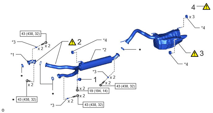
COMPONENTS (INSTALLATION)
A483482N01
3.875,2.813 4.573,3 0.698,0.188 2.792,3.438 3.49,3.625 0.698,0.188 0.552,3.26 1.25,3.448 0.698,0.188 0.677,1.042 1.375,1.229 0.698,0.188 2.969,2.969 3.667,3.156 0.698,0.188 1.865,2.156 2.083,1.406 false 1.208,2.083 2.094,1.396 2.094,1.396 2.302,1.396 false 0.531,1.833 0.698,1.833 0.698,1.833 0.948,2.104 false 3.052,2.042 3.208,1.677 3.208,1.677 3.396,1.677 false 6,1.458 6.26,1.781 6.26,1.781 6.417,1.781 false 4.188,1.667 4.583,1.667 false 1.76,2.833 1.354,2.833 1.354,2.833 1.354,2.177 false 1.771,2.698 1.771,3.042 false 0.729,2.458 0.729,2.24 false 0.896,3.25 0.896,2.74 false 2.792,3.521 2.625,3.521 2.625,3.521 2.625,3.26 false 1.552,1.396 1.552,1.135 1.552,1.135 1.375,1.135 false 6.875,0.208 6.615,0.208 false 3.396,2.896 3.875,2.896 false 2.729,2.677 3.083,2.677 false 2.625,3.063 2.969,3.063 false 5.729,1.833 5.99,2.156 5.99,2.156 6.146,2.156 false 6.302,0.615 6.563,0.938 6.563,0.938 6.719,0.938 false 2.458,1.729 3.26,1.344 3.26,1.344 3.417,1.344 false 3.281,2.417 3.448,2.417 3.448,2.417 3.625,2.594 false 0.573,1.406 0.74,1.406 0.74,1.406 1.208,1.573 false 1.875,3.552 2.042,3.552 2.042,3.552 2.24,3.344 false 3.135,2.531 3.417,2.885 0.281,0.354 18 false 1 2.604,1.26 2.885,1.615 0.281,0.354 18 false 2 6.719,1.646 7,2 0.281,0.354 18 false 3 1.51,1.458 1.969,1.656 0.458,0.198 10 false x 2 2.677,3.146 3.135,3.344 0.458,0.198 10 false x 2 0.938,2.771 1.396,2.969 0.458,0.198 10 false x 2 3.542,2.708 4,2.906 0.458,0.198 10 false x 2 3.698,2.521 4.156,2.719 0.458,0.198 10 false x 2 6.365,0.479 6.823,0.677 0.458,0.198 10 false x 3 2.677,2.896 3.135,3.094 0.458,0.198 10 false x 2 0.354,1.76 0.667,1.958 0.313,0.198 10 false *1 3.448,1.594 3.76,1.792 0.313,0.198 10 false *2 0.688,2.458 0.844,2.656 0.156,0.198 10 false ● 1.74,3.063 1.896,3.26 0.156,0.198 10 false ● 4.667,1.573 4.823,1.771 0.156,0.198 10 false ● 6.438,0.094 6.719,0.448 0.281,0.354 18 false 4 0.406,3.26 0.563,3.458 0.156,0.198 10 false ● 3,2.99 4.469,3.146 1.469,0.156 8 false 19 (194, 14) 3.917,2.833 4.625,3.01 0.708,0.177 8 false 43 (438, 32) 2.844,3.458 3.552,3.635 0.708,0.177 8 false 43 (438, 32) 0.594,3.281 1.302,3.458 0.708,0.177 8 false 43 (438, 32) 0.719,1.063 1.427,1.24 0.708,0.177 8 false 43 (438, 32) 1.271,1.552 1.729,1.75 0.458,0.198 10 false x 2 2.281,3.323 2.74,3.521 0.458,0.198 10 false x 2 3.115,2.333 3.427,2.531 0.313,0.198 10 false *3 6.198,2.083 6.51,2.281 0.313,0.198 10 false *4 6.771,0.854 7.083,1.052 0.313,0.198 10 false *4 3.469,1.271 3.781,1.469 0.313,0.198 10 false *4 0.396,1.333 0.708,1.531 0.313,0.198 10 false *3 1.698,3.469 2.01,3.667 0.313,0.198 10 false *3

Procedure Part Name Code
Z101186

Z101188

Z101187

1 EXHAUST PIPE DAMPER 17581A - - -
2 FRONT AND CENTER EXHAUST PIPE ASSEMBLY - (Click here) - -
3 TAIL EXHAUST PIPE ASSEMBLY 17430 (Click here) - -
4 INSPECT FOR EXHAUST GAS LEAK - (Click here) - -

*1 FRONT EXHAUST PIPE ASSEMBLY *2 CENTER EXHAUST PIPE ASSEMBLY
*3 COMPRESSION SPRING *4 EXHAUST PIPE SUPPORT
V100146

N*m (kgf*cm, ft.*lbf): Specified torque ● Non-reusable part

CAUTION / NOTICE / HINT

NOTICE:

Perform "Inspection After Repair" after repairing an exhaust gas leak.

Click hereEngine / Hybrid System>V35A-FTS (ENGINE CONTROL)>SFI SYSTEM>INITIALIZATION


PROCEDURE

Hide 17581A 1.INSTALL EXHAUST PIPE DAMPER

Torque:
19 N*m (194 kgf*cm, 14 ft.*lbf)

Hide 2.INSTALL FRONT AND CENTER EXHAUST PIPE ASSEMBLY
a.
A487001N01
0.448,0.083 1.823,0.438 1.375,0.354 18 false i, ii

i.

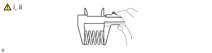
Using a vernier caliper, measure the free length of the compression spring.

Minimum length:

43 mm (1.69 in.)


ii.

If the free length is less than the minimum, replace the compression spring.


b.
A483487C01
4.479,1.5 4.688,1.5 4.688,1.5 5.104,1.281 true 5.458,0.74 5.906,0.74 true 4.292,1.427 4.604,1.625 0.313,0.198 10 false *1 5.979,0.656 6.292,0.854 0.313,0.198 10 false *a 0.458,0.083 1.25,0.406 0.792,0.323 18 false i, ii
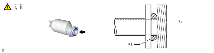
*1 Gasket - -
*a Wooden Block - -


i.

Temporarily install 2 new gaskets to the converter assembly RH and converter assembly LH.


ii.

Using a plastic-faced hammer and wooden block, tap in the 2 gaskets until its surface is flush with the converter assembly RH and converter assembly LH.

NOTICE:
·

Be sure to install the gasket so that it faces the correct direction.

·

Do not reuse the gasket.

·

Do not damage the gasket.

·

When connecting the front exhaust pipe assembly and center exhaust pipe assembly, do not push in the gasket with the front exhaust pipe assembly and center exhaust pipe assembly.


c.
A483488N01
2.354,1.281 2.479,1.458 0.125,0.177 10 true 1 2.552,1.563 2.677,1.74 0.125,0.177 10 true 1 2.083,1.083 2.208,1.26 0.125,0.177 10 true 1 2.021,0.49 2.146,0.667 0.125,0.177 10 true 1 2.969,1.469 3.094,1.646 0.125,0.177 10 true 2 2.625,0.854 2.75,1.031 0.125,0.177 10 true 2 3.26,0.948 3.448,1.229 0.188,0.281 18 true i 1.708,0.073 2.531,0.365 0.823,0.292 18 true iii, iv, v 4.677,0.854 4.885,1.156 0.208,0.302 18 true ii

i.

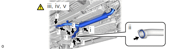
Install the center exhaust pipe assembly to the exhaust pipe support.


ii.

Install a new gasket to the center exhaust pipe assembly.

NOTICE:

Do not reuse the gaskets.


iii.

Temporarily install the front exhaust pipe assembly to the center exhaust pipe assembly with 2 new bolts.


iv.

Temporarily install the front exhaust pipe assembly and center exhaust pipe assembly to the converter assembly RH and converter assembly LH with the 4 compression springs and 4 bolts.


v.

Tighten the 6 bolts in the order shown in the illustration.

Torque:
43 N*m (438 kgf*cm, 32 ft.*lbf)


Hide 17430 3.INSTALL TAIL EXHAUST PIPE ASSEMBLY

a.
A487001N01
0.448,0.083 1.823,0.438 1.375,0.354 18 false i, ii

i.

Using a vernier caliper, measure the free length of the compression spring.

Minimum length:

42 mm (1.65 in.)


ii.

If the free length is less than the minimum, replace the compression spring.


b.
A483485C01
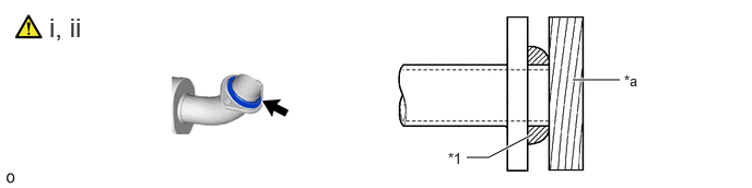
4.448,1.5 4.656,1.5 4.656,1.5 5.073,1.281 true 5.458,0.76 5.906,0.76 true 4.271,1.427 4.583,1.625 0.313,0.198 10 false *1 5.948,0.688 6.26,0.885 0.313,0.198 10 false *a 0.469,0.115 1.26,0.438 0.792,0.323 18 false i, ii
*1 Gasket - -
*a Wooden Block - -


i.

Temporarily install a new gasket to the center exhaust pipe assembly.


ii.

Using a plastic-faced hammer and wooden block, tap in the gasket until its surface is flush with center exhaust pipe assembly.

NOTICE:
·

Be sure to install the gasket so that it faces the correct direction.

·

Do not reuse the gasket.

·

Do not damage the gasket.

·

When connecting the tail exhaust pipe assembly, do not push in the gasket with the tail exhaust pipe assembly.
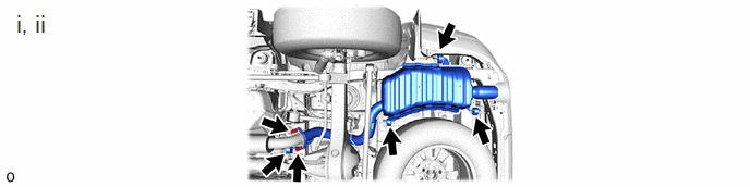


c.
A483486N01
0.135,0.094 0.552,0.427 0.417,0.333 18 false i, ii

i.

Install the tail exhaust pipe assembly to the 4 exhaust pipe supports.


ii.

Connect the tail exhaust pipe assembly to the center exhaust pipe assembly with the 2 compression springs and 2 bolts.

Torque:
43 N*m (438 kgf*cm, 32 ft.*lbf)


Hide 4.INSPECT FOR EXHAUST GAS LEAK

a.

If gas is leaking, tighten the areas necessary to stop the leak. Replace damaged parts as necessary.


b.

Perform "Inspection After Repair" after repairing an exhaust gas leak.

Click hereEngine / Hybrid System>V35A-FTS (ENGINE CONTROL)>SFI SYSTEM>INITIALIZATION